This thread has been locked.

If you have a related question, please click the "Ask a related question" button in the top right corner. The newly created question will be automatically linked to this question.

TPS7B7702-Q1: VIN=12-16V, Vout=12V

Part Number: TPS7B7702-Q1
Other Parts Discussed in Thread: TPS7B7702

Dear team,

My customer application condition is as below,

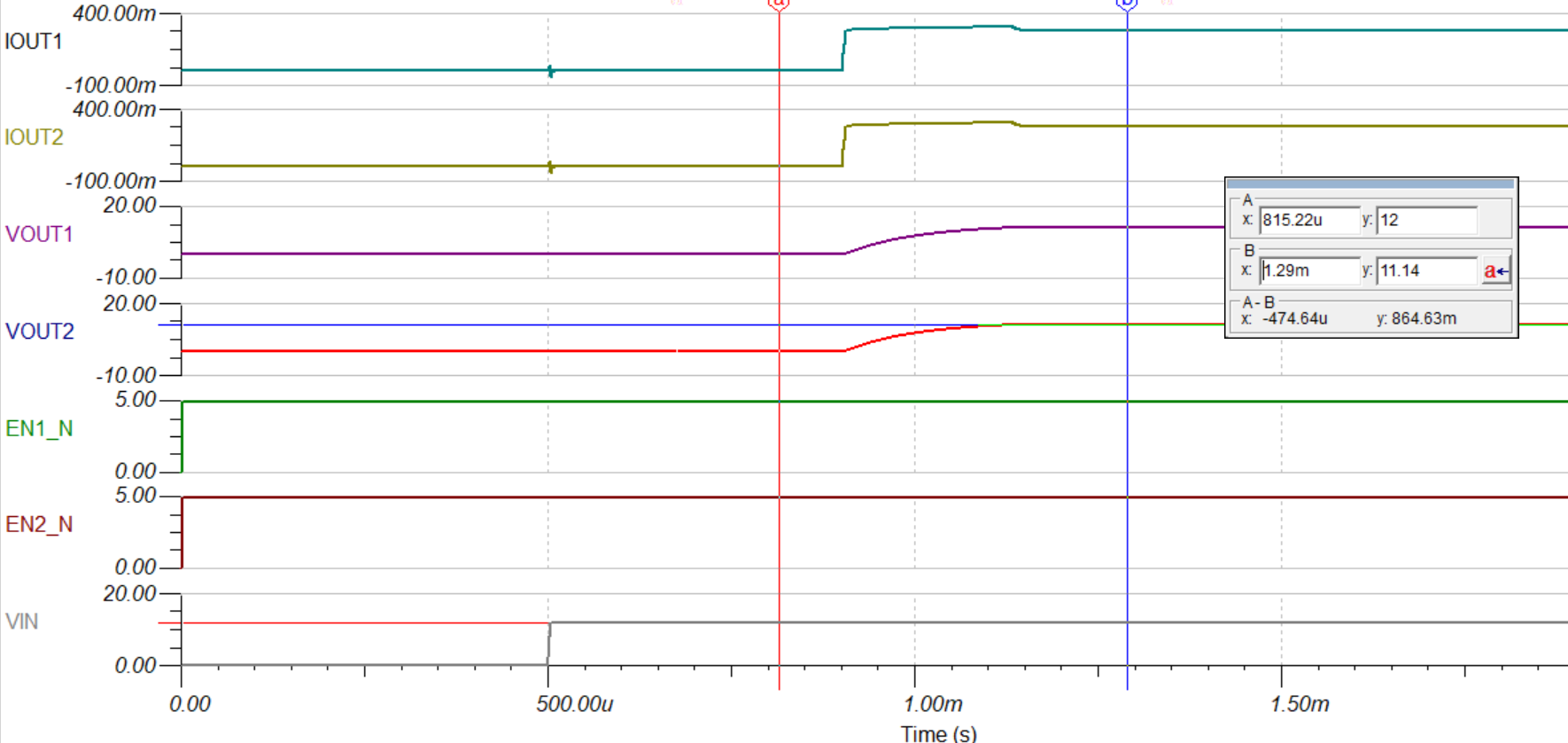
VIN=12V-16V, VOUT=12V, Iout=600mA, 1ch. Therefore we plan to connect two outputs together, in this way we have 600mA load current capacity. My customer wants to know what the output is when VIN=12V, and they want to know the max dropout. I use TINA to simulate this as below. Vin=12V, Vout=11.14V. Is this data credible?

TPS7B7702-Q1.tsc

Thanks & Best Regards,

Sherry

  • Hi Sherry,

    I believe if you want to connect the outputs together you will need to treat it the same as connecting 2 discrete LDOs together, i.e. there will need to be a ballast resistor at the output of each. The TINA simulation seems fine because in the sim the outputs can be exactly the same, but in a real circuit there will be small errors that cause the outputs to be different. If there is not a ballast resistor the LDOs will fight each other and the best case scenario is that the output can oscillate, and in the worst case the IC can be destroyed. See the following reference design, which shows how to correctly connect the outputs of LDOs and how to size the ballast resistor:

    High-Current, Low-Noise Parallel LDO Reference Design

    Regards,

    Nick

  • Hi Nick,

    Thanks for your reply!

    Based on this document, I try to compute the ballast resistors, but the result is around 4ohm which is too large.

    VIN-12-16V, Vout=12V, Iout=600mA. Could you please help check below computation?

    E_VOUT=E_VREF+2*(1-Vref/Vout_nom)*Erfb=1.233*1%+2*(1-1.233/12)*Erfb, but I don't understand what the Erfb is? Is it 1%? If I set it as 1%, then E_VOUT=0.003.

    Then R_ballast=Vout_nom*2*E_VOUT/(2*IoutMaxSingle-IoutMaxTotal), if IoutMaxSingle=0.4A and IoutMaxTotal=0.6A, then R_ballast=3.6ohm.

    Thanks & Best Regards,

    Sherry

  • Hi Sherry,

    When I put in the numbers for E_VOUT as you have described them, I calculate 0.03V, I think that is a typo because following through the rest of it makes sense using 0.03V. However, I think the correct error for Vref is 2% instead of 1%. For Erfb, I believe the correct way is to assume the worst scenario to calculate the maximum error. For example, if we used 0.01% resistors, the worst case would be if R2 was 0.01% over and R1 was 0.01% under, and the total error would be 1.0001/0.9999 = 1.0002, or 0.02% error. 

    Using 0.01% resistors, I calculate E_VOUT = 1.233*2% + 2*(1-1.233/12)*0.02% = 25mV

    That makes R_ballast = 12*2*25mV/(2*.4 - .6) = 3Ω

    Here's the thing that I think is making the R_Ballast too large. Since we are wanting to operate near the current limit of both channels the term 1/(2*I_outMaxSingle - I_outMaxTotal) is also large. I'm also not sure that I_outMaxSingle = 0.4A is the correct number to use because the max current limit is 300mA. 

    Even if Erfb was zero, the E_VOUT is largely dominated by the error in Vref, and E_VOUT = 1.233 * 2% = 24.66mV. We could probably live with the error of the Vref, but R_ballast gets very large when the device is operating near its current limit. I think that this probably will not work because of the lack of headroom for output current vs. current limit. 

    Regards,

    Nick