This thread has been locked.

If you have a related question, please click the "Ask a related question" button in the top right corner. The newly created question will be automatically linked to this question.

UA78L: UA78L05AI spec question and parameter definition questions

Part Number: UA78L

Hi Team, 

My customer is considering UA78L05AI now. He has following questions. Please kindly help. Thanks.

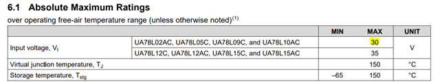
1. What is absolute maximum rating of Input voltage? Is it 30V?

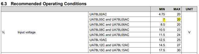
2. What is Recommended Operating Conditions of Input voltage? Is it between 7V~20V?

3. What does following parameter mean?

Output voltage regulation : Does it mean voltage deviation from required value? For example, if this parameter is 60mV and output is 5V, real value may be 5V±60mV? 

Output noise voltage : What does it mean and what does this affect?

Dropout voltage : Does it mean the min voltage between Vin and Vout needed to use this LDO? For example, Vin have to be 1.7V bigger than Vout in this case?

Thanks.

Regards,

Jo

  • Hi Jo,

    1) 30V

    2) 7V-20V

    3) Output voltage regulation: Output voltage regulation is how much the voltage may deviate from ideal value. So yes you can think of it as ±15mV at current limit.

    Output noise voltage: Output noise voltage is the spectral noise density integrated and represented in Vrms. So in this parts case over the frequencies 10Hz to 100kHz were measured at 25C and 42uVrms was the integrated value of that noise. This means that those frequencies are present on the LDO's output voltage at a scale of 42uVrms. As for it's effect that is up to the system level use case. It is merely a representation of the noise present at the VOUT pin of the device. The total value of the noise is very small, but if the use case of the system is very sensitive to these frequencies then you may need additional damping at the relevant frequencies through Cout impedance matching. They will most likely not need to do this as one of LDO's strongest qualities are very clean outputs.

    Dropout voltage: Dropout voltage is the voltage from Vin to Vout when the part is in dropout operation, not standard operation. that means the part is not regulating the standard output voltage, and Vout = Vin - 1.7V. For this part to operate with 5V out safely, we recommend a Vin min of 7V, that is why in our recommended operating conditions we list 7V-20V.

    Regards,

    John

  • Hi John, 

    Thank you for the detailed explanation! 

    Customer wants to know UA78L05AI's power dissipation(absolute max. rating), 

    could you tell us how much or how can we get it?

    Thanks.

    Regards,

    Jo

  • Hi Jo,

    The first part is raw power dissipation maximum, that would be at max current, and max Vin. So (20V-5V)*0.1A = 1.5W of power dissipation. But one thing that they need to consider is the thermals of the board they are going to apply it on. At 1.5W of dissipation using the SOIC package gives a junction to ambient temperature rise above ambient of 172.5C. Using the SOT-89 package the rise above ambient would be 82.05C. So there are concerns operating at maximum power dissipation, at steady state, if they do not take the proper precautions in thermal management.

    Linked here is a great resource to help them understand ways they can improve thermal performance on their board.

    Regards,

    John

  • Hi John, 

    I understood real power dissipation that UA78L can handle depends on board layout. 

    Customer is using UA78L05AILPR so it's TO-92 package and absolute max. rating for UA78L is 150C. 

    Can we say absolute max. rating of power dissipation is 0.87W from following calculation if Ta=25C?

    Tj(150C)=Ta(25C)+Rth-ja(143.6C/W)*Pd

    Pd=0.87W

    Or do we have a chart like below for UA78L05AILPR?

    Thanks.

    Regards,

    Jo

  • Hi Jo,

    Yes, your math is correct, but I would use 125C as they should not operate at 150C in steady state, that is merely the abs max the part can go without permanent damage from overtemp. Abs max power dissipation is usually not a concern, it is more so line and load transients that are the concern that overvoltage's will occur. If they are asking for an abs max Pd then yes 0.87W would be that value, but 125C is the highest we recommend customers operate. So the maximum power dissipation would compute out to Pd = 0.696W. We do not have a chart like that as it's just a linear function, and it adjusts with each package.

    However this maximum power is only for the JEDEC standard board. Using the app note on board design to improve thermal performance can, and will, decrease the thermal resistance of the part, allowing the allowable total power dissipation to go up.

    Regards,

    John