Other Parts Discussed in Thread: TPS546D24A, TPS546D24
I'm using the TPS546D24AEVM-2PH to test configurations before programming actual boards. I am running into some problems:
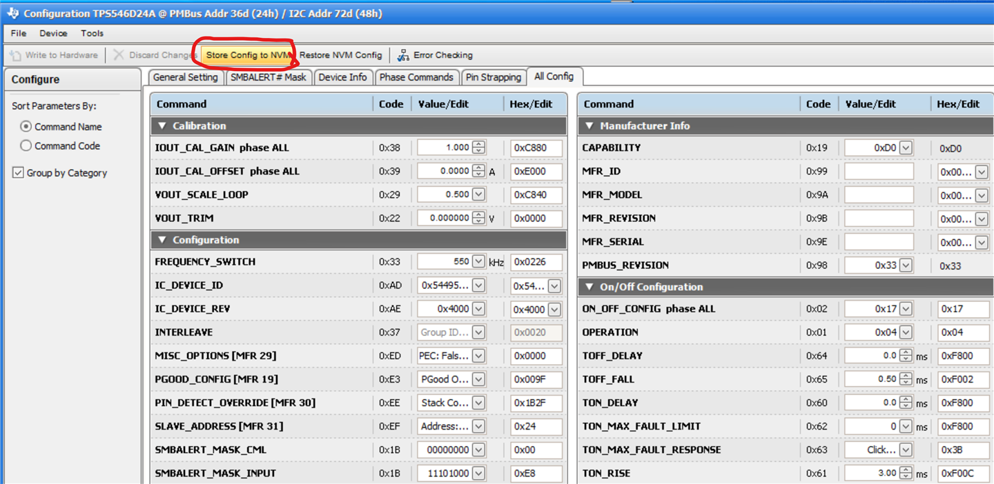
- The power controller is reporting an IOUT of about 22 A, even though the actual IOUT is only about 1.6 A. The input and output voltage reported by the power controller are correct. Also, the IOUT reported by the phases is assymetrical with PH1 = 16.5 A and PH2 = 5.5 A. (IOUT_CAL_GAIN = 1 and IOUT_CAL_OFFSET = 0.)
- The IOUT UC Fault alert is active. I see no threshold setting for this in the register set and cannot understand what would qualify as an undercurrent.
- I had to set all FAULT_RESPONSEs to "Continue Without Interruption" to keep the controller from hiccuping. After the output became stable, I changed the FAULT_REPSONSEs again to "Shut Down Immediately" and the output remained unaffected. I don't know which FAULT_RESPONSE caused the hiccuping.
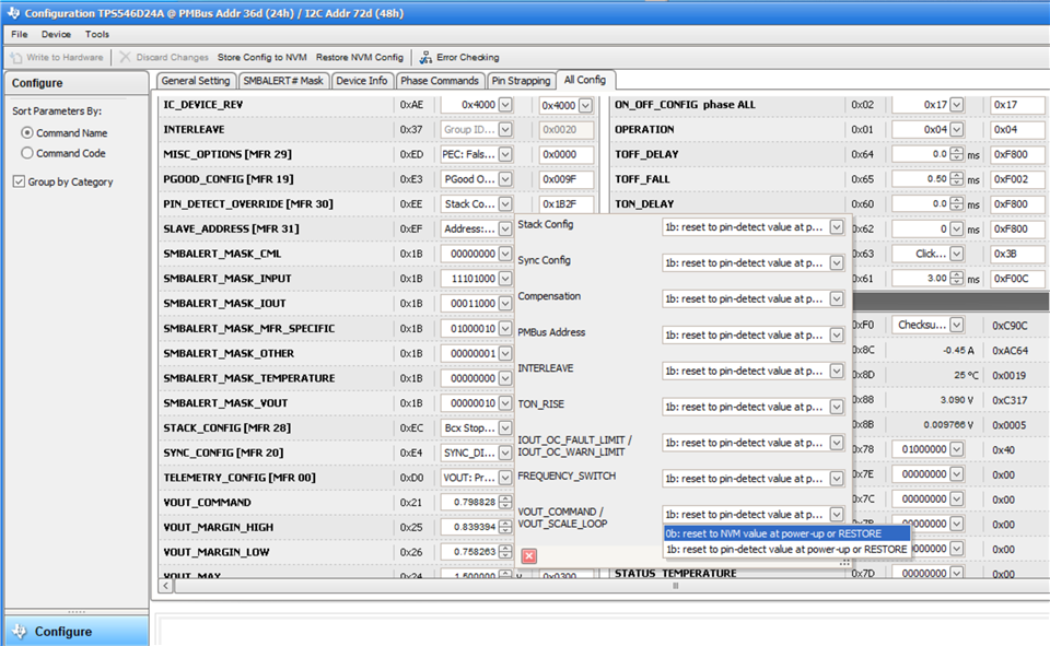
- Although set to 400 mV output in the NVM, the power controller frequently defaults to 800 mV output. NVM values do not seem to stick.
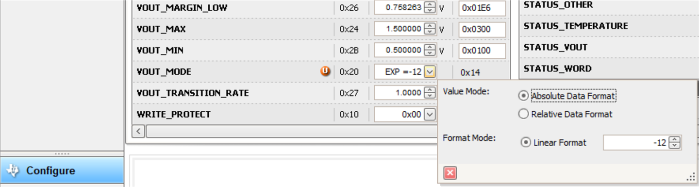
I have read through the EVM user manual and power controller register descriptions. The EVM is in the factory default configuration. All of the register values make sense. OPERATION and ON_OFF_CONFIG are at default values. VOUT_SCALE_LOOP is 1, FREQUENCY_SWITCH is 325 kHz. I am using Absolute Data Format for VOUT_MODE and E-12 linear format.
Please help me to debug these issues. Thank you!