This thread has been locked.

If you have a related question, please click the "Ask a related question" button in the top right corner. The newly created question will be automatically linked to this question.

TPS2115A: Auto switching between input sources

Part Number: TPS2115A
Other Parts Discussed in Thread: TPS2113A, , TPS2116, TPS2121, TPS22953

Hi Team,
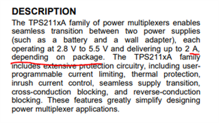
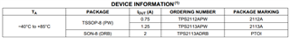
I am using TPS2115APWR in one of my circuits.
I have 2 batteries as voltage sources (primary and secondary battery).
I want automatic switching between my input power sources for that I am shorting D1 to GND and D0 to high so that the battery with higher voltage will be connected to the output load.
If my batteries are nearly at the same voltage, my load is going to swing between two inputs and I don't want that to happen.
If D0 is connected to GND, the loads will be power from the primary battery or secondary battery based on the voltage at the D1 pin.
I was planning to set a voltage divider at the D1 pin from the primary battery so that when the voltage at the primary battery balls below a particular level, the output of the divider will be less than 0.7V(VOL) of the chip.
My battery voltage will be in the range of 3V to 4.2V.
It is difficult to build such a voltage divider to get a voltage greater than 2V(VOH) of the chip if the battery voltage is greater than 3.5V and less than 0.7V (VOL) when the battery voltage is less than 3.5V.
Is there any solution for this?.
A Schmitt-Trigger could work, but a Schmitt-Trigger of the same specification is difficult to find??.

  • Hi Shibin, 

    To trigger a switchover when the primary battery falls below a particular level, you can tie D0 to IN1 through a resistor divider. In this state, IN1 and IN2 will be compared with one another as usual. The resistor divider could be setup so as to pull D0 low whenever IN1 goes below a certain voltage and in this state (D1 and D0 low) the device will select IN2. You don't necessarily have to hit the VOL threshold of the device for the switchover to work. If in this case, if you are still experiencing a voltage swing of constant switchover, another option is to consider the following alternative devices: 

    1. The TPS2113A: This device is similar to TPS2115A and in the same package and has similar pins and has a tighter tolerance for the voltages resulting in less time when Dx pins have an voltage which is in between V_il and V_ih.

    2. The TPS2116: TPS2116 is a new generation low Iq powerMUX. It can be used to set priority and a user set hysteresis window that can be used in your application where your input voltages are similar. This device can also handle more current and switches faster than older TPS211xA devices.

    Best Regards, 

    Elizabeth

  • Hi Elizabeth
    Thank you for your reply.

    About TPS2115A.
    If we are connecting the pin D1 to 0V and a voltage divider from the IN1 to the D0 pin, so that a logic 0 (<0.7V) when the battery voltage is less than 3V on the D0 pin can be designed. But the same voltage divider can't give a logic 1 (>2V) when my battery voltage is greater than 3V.
    If D1 and D0 are at logic 0 and logic 1 respectively, the load will be power from the battery with higher voltage and if batteries are of the same potential, the load is gonna swing between the inputs.
    Please correct me if I am wrong

    About TPS2116.
    The same is not available in Mouser it DigiKey, so I am left with TPS2113A.

    About TPS2113A.
    Since the voltage at the Vsens pin is compared with the 0.8V reference, I believe a voltage divider from the IN1 to the Vsens pin can do the trick. The voltage diver will be set such that the voltage at the Vsens pin will be greater than 0.8V when the battery voltage is greater than 3V so that IN1 will be selected and the voltage at the Vsens pin will be less than 0.8V when my battery voltage is less than 3V so that IN2 will be selected.
    I hope the 8-TSSOP package can handle up to 2 A of current.
    Is there any power mux, Ideal diode available with a current rating greater than 3.5A?

  • Hi Shibin, 

    Neither the TPS2113A nor TPS2115A can support 2A of current. Both the TPS2113A and TPS2115A devices are only rated for 1.25A.

    Is 2A of current to the output needed for your application? 

    If 1.25A is acceptable, I would recommend the TPS2113A ahead of the TPS2115A. 

    Our TPS2121 device can supply a current up to 4.5A, however this device is also out of stock on Mouser. 

    Best Regards, 

    Elizabeth 

  • Hi Elizabeth,
    Thank you for your reply.
    Below is a snap from the datasheet of TPS2113A

    Can you suggest to me a power mux/switch continuous current rating of more than 3.5A

  • Hi Shibin,

    The TPS211XA family of power muxes can supply 2A in a SON-8 (DRB) package, but not the 8-TSSOP package. 

    In this SON-8 package, the abs max Continuous output current is actually 2.5A. 

    Our only power mux devices that over a current rating of more than 3.5A are the TPS2116 and TPS2121.

    Best Regards, 

    Elizabeth 

  • Hi Elizabeth,
    Thank you for your reply.
    Both TPS2116 and TPS2121 are not available in Mouser or DigiKey.
    I have 2 battery sources (4.2V). I only want the second battery to discharge when the first battery is discharged to about 3V.
    Since the voltages are the same in both the batteries, an ideal diode will oscillate between the input battery sources. What is the best solution that can be implemented here?.

  • Hi Shibin, 

    Two load switches can be used to mux the two supplies. Any two load switches can be used in the configurations specified in the document below as long as they have reverse current blocking and no quick output discharge. 

    However, these do not support over 3.5A current draw. Is 3.5A needed? If so, we have the TPS22953 however they seem to also be sold out on Mouser.

    https://www.ti.com/lit/an/slvae51a/slvae51a.pdf?ts=1631827374349&ref_url=https%253A%252F%252Fwww.ti.com%252Fpower-management%252Fpower-switches%252Fpower-muxes%252Foverview.html%253FkeyMatch%253DPOWER%2BMUX

    Best Regards, 

    Elizabeth