This thread has been locked.

If you have a related question, please click the "Ask a related question" button in the top right corner. The newly created question will be automatically linked to this question.

TPS54528: Humming Noise Problem

Part Number: TPS54528
Other Parts Discussed in Thread: TPS54527

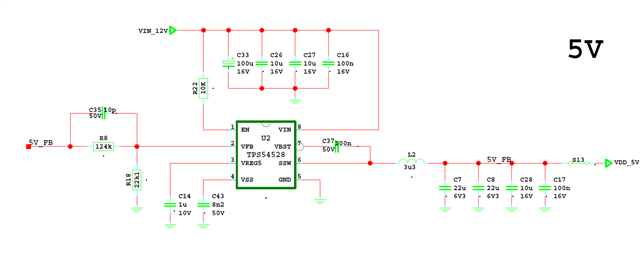
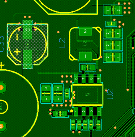
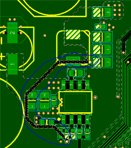
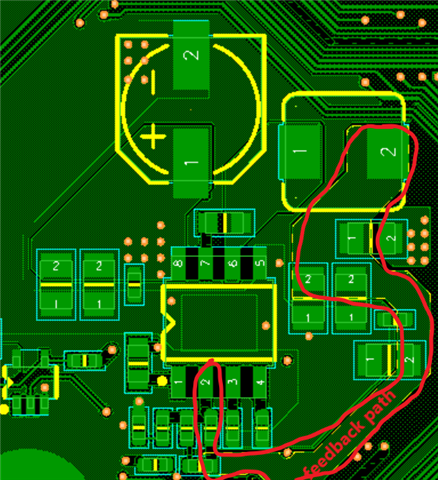
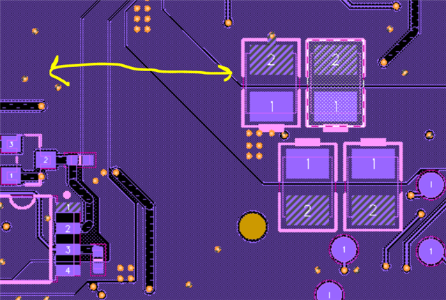
Hi, In TPS54528 we use in our custom board design, we encounter humming noise problem and out-of-spec ripple in output voltage. Can you help with the subject? I am sharing the relevant part of our schematic and layout. 

  • Utku,

    • Is it possible to share the VIN, SW and VOUT steady-state waveforms when the humming noise is present? Since you mention out of spec ripple voltage, I would like to see 10 cycles of waveforms with a 1x or 10x scope probe in AC coupling mode with 1Mohm impedance.
    • What is the load current at which you are testing? Does the humming noise go away if you increase the load current (so the device is operating in CCM)?
    • You might also need to take a look at the inductor and input/output ceramic caps -
      • what is the inductor part number? Shielded inductors are recommended - you can try XAL, XFL or the latest XGL coilcraft series.
      • The output capacitors 2x22uF have a very low VDC rating of 6.3V for a 5V design which will cause significant derating and loss of capacitance. I recommend changing those 2x22uF caps to be of VDC rating 16V or higher. Please try changing this
    • On the layout, how is the FB trace routed from the feedback resistors to VOUT? Please check EVM UG as a reference for this as well as other component placement. 

    Thanks,

    Amod

  • Hi Amod,

    Thanks for your detailed help. I will try to send the measurement results during the day. By the way, our 5V output feeds several places and there are decoupling capacitors at the input of these places, do we consider them as output capacitors? 22-68 uF is recommended as output capacitor of the buck. If we include the decoupling capacitances of the places fed 5V, we exceed this value very much, about 150 uF.

  • Here is the feedback trace:

  • Hi Utku,

    The other decoupling caps connected to the 5V output are not placed close to the IC. It would be a good idea to replace the 2x22uF with higher VDC rating caps to see if it improves stability on VOUT ripple. The FB trace should be routed like Figure 5-5 in EVM away from SW node and inductor.

    Thanks,
    Amod

  • Thank you so much, we'll consider your reviews. We have another DC-DC part with TPS54528 in our custom board, the problem is there is bigger than the part that I've asked help before (12V-5V). There is some unwanted oscillations even in no-load condition. In this part we convert 12V to 3.8V for supplying 2G/3G/4G module and have bigger decoupling capacitors about 600 uF at the input.  As you said before, these capacitors are not at the output of the converter but near to the converter as follows. Do this capacitors effect stability of the converter? Or is it a bigger problem that the feedback path is as follows?

    And layout is like that: 

    Can you help with this part as well, I will appreciete for your help.

  • Hi Utku,

    TPS54528 runs in eco mode at low load conditions and that frequency can be quite low and ripple will be higher. You can try the TPS54527 pin-to-pin compatible part for TPS54528 which does not have eco mode. The high 600uF caps can cause instability but usually since they are not close to the IC, the trace resistance helps with damping the q-factor of the effective LC double pole. As mentioned earlier, you can ensure there is enough cap (22uF-68uF as per datasheet) near the IC by making sure VDC rating on the 2x22uF is 16V or higher and also see if FB trace routing can be improved to stay far from SW and inductor.

    Thanks,
    Amod