This thread has been locked.

If you have a related question, please click the "Ask a related question" button in the top right corner. The newly created question will be automatically linked to this question.

BQ24130: Reverse current protection

Part Number: BQ24130

Hi Team,

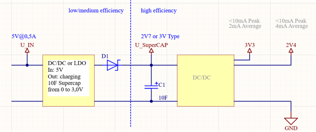
Our customer is looking a 3V supercapacitor charger from a 5V supply with 0.5A maximum current. Their loads will consume an average current of 2mA and 4mA  and peak current of less than 10mA. One of the supercapacitor battery charger that we have stocks is BQ24130. Referring to Figure 2 of the datasheet, it appears that the device has no reverse current protection. Can we add a reverse current protection diode (D1) as shown in the figure below? 

Regards,

Danilo

  • Dear Danilo,

    Please take a look at Figure 1. It has Q3 and Q4 where Q3 is a reverse blocking FET. You could implement just a diode here as well.

    Thanks,

    Mike Emanuel

    Please click "Resolved" if this answered your question.

  • Hi Mike,

    The typical application circuit in Figure 1 is for charging battery while Figure 2 is for charging supercapacitor. Since the customer's application is charging a supercapacitor, I will refer to Figure 2. I understand that when the adapter is removed, the reverse current will flow to the voltage divider R12 and R11 as well as the pins SRN, SRP and SW. Our customer is concerned that the reverse current could be significantly high that it will discharge the supercapacitor faster.

    How much is the reverse current and do we need to add a reverse current protection diode (D1) before the supercapacitor as shown in the diagram above?

    Regards,

    Danilo

  • Dear Danilo,

    Although Figure 1 is for charging battery, the same principle of a reverse blocking diode carries over.

    The I(BAT) specification is the battery discharge current into AVCC, BTST, SW, SRP, SRN, and BAT.

    1. The battery discharge current specification, I(BAT) is 15 uA max if the AVCC voltage is less than the UVLO voltage.

    2. If the AVCC voltage is greater than the UVLO voltage, but still less than the SRN voltage, the I(BAT) is still 15 uA max.

    Please see the specification for more details.

    Adding a diode is not recommended in the charging path, as it will present a roughly 0.7 V drop against the 0.5 A charge current yielding a loss of 350 mW on the diode.

    The amount of current that will flow into BAT is above, while the amount of current that flows through the BAT resistors R12 and R11 depends on the resistors themselves as well as the output voltage.

    Thanks,

    Mike Emanuel

    Please click "Resolved" if this answered your question.