Other Parts Discussed in Thread: TPS27082L,
Hi,
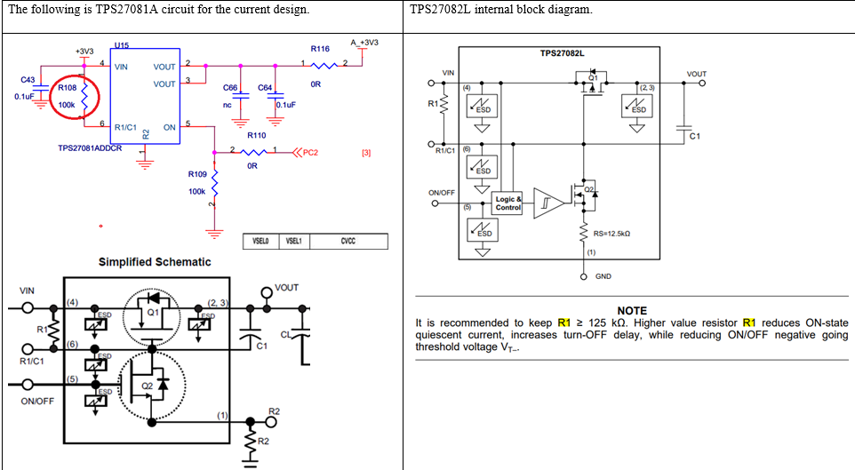
We are trying to use TPS27082L as an alternative source for the TPS27081A.
In the characteristic and peripheral circuit of components portion, does there any concerns we need to pay attention to?
Do we can install TPS27082L on the location U15 directly and keep the peripheral circuit setting?
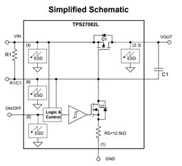
The TPS27082L internal block diagram as following table's right side.
If we want to achieve maximize the ON-state Vgs-q1 and minimizes Vin to Vout voltage drop.
The better R1 value is 10 times as R2, Right?
So, base on our peripheral circuit of U15
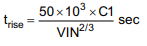
TPS27081A equation:
Vgs-q1 = -3.3V*(100K / (100K+0)) = -3.3V, Rds(on) around < 44m ohm
TPS27082L equation:
Vgs-q1 = -3.3V*(100K / (100K+12.5K)) = -2.93V, Rds(on) around > 44m ohm
Thanks!
Jeff