This thread has been locked.

If you have a related question, please click the "Ask a related question" button in the top right corner. The newly created question will be automatically linked to this question.

LMV431: Need help designing a cap discharge circuit

Part Number: LMV431
Other Parts Discussed in Thread: TINA-TI, TL431LI

Hello,

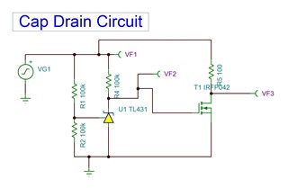
   I've played around with this and haven't come up with a good solution yet. I have a project that is battery powered (nominal 12V - 24V) but when the battery is removed I want to discharge all the caps on the board. I figured out that I need the LMV431 because of its wider Vin range and lower current requirements, but not sure how to connect it. I want this circuit to kick in when the rail voltage gets below 5V, and discharge through a 100 ohm resistor.

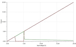
I've tried to use TINA-TI and did my best. See attached image. Will this work?

Shunt voltage will be set with Rtop/Rbot = 10k/10k which gives me a reference voltage of 5V.

Iref needs to be at least 0.5uA; current through Rbot+Rtop (20k total) at 5V is 250uA so that should be good. I used 100k in the simulation just to see.

Cathode current for LMV431 must be at least 100uA. At 3V, R=30k; at 24V, R=240k. So for no we will use 10k to set cathode current at minimum of 300uA at 3V or 2.4mA at 24V.

Error of 10% on voltage threshold is fine. Temperature range of the product is -10C to 40C.

Question: will this work? Is there an easier way to do this?

Question: What is the highest value of Rtop & Rbot that I can use to meet the minimum Iref for the TL431LI? These resistors are going to drain current continually so I want to minimize that current.

Thanks,

Derek

  • Hi Derek,

    I dont believe the image made it through.  Can you try to upload the picture again?

    Ben

  • Image attached - but I think I'll use a FET with a 1.5V threshold so there's less of a "bump" below 2.5V.

    I also attached the TINA-TI model.

      TL431 Cap Drain Circuit.TSC

  • Hi Derek,

    Question: will this work? Is there an easier way to do this?

    Yes, your idea will work.  You are using the LMV431 as a comparator to turn on the FET to drain the capacitors.

    Question: What is the highest value of Rtop & Rbot that I can use to meet the minimum Iref for the TL431LI? These resistors are going to drain current continually so I want to minimize that current.

    The highest value of Rtop will depend on what is the lowest voltage of VG1.  I believe it was mentioned that 3V.  According to the LMV431 datasheet, the typical current for Iref is 0.15uA.  My take is to set current first by determining the resistor value for Rbot.  That is determined to be (1.24V / Rbot).  For simplicity, we can set the current for 1uA.  Therefore, the total current that flows through Rtop will be 1uA + 0.15uA = 1.15uA.  Knowing the current through Rtop, you can calculate the Rtop resistor [(3V - 1.24V) / 1.15uA]  

    I hope this helps.

    Ben

  • Hi Derek,

    Just following up with you to see if you have any other questions.  If not, can you close the thread by clicking on "resolved"?  Thanks!

    Ben