


Noise is a long-standing enemy of high speed circuits. Whether it is noise on a power rail or at the gate of a power FET, noise can cause unpredictable behavior and even irreparable damage. Ferrite beads are one of the tools engineers have to combat such noise. This FAQ explains first what ferrite beads are and how they behave, and then describes where to use ferrite beads in gate drive circuits, and finally what must be taken into account when selecting a ferrite bead.
What is a ferrite bead?
Simply put, a ferrite bead is a wire surrounded by a ferrite, a ceramic material with magnetic properties. In its simplest form a ferrite bead consists of a wire inserted through hollow bead of ferrite. What makes ferrite beads significant is how they behave in a circuit. Ferrite beads exhibit a frequency dependent combination of resistive, capacitive, and inductive properties. Generally, at low frequencies the inductive component is dominant, but as frequency approaches the resonant frequency ferrite beads become resistive. At very high frequencies the capacitive element becomes dominant. An equivalent circuit model that demonstrates the resonant behavior of a ferrite bead is shown in Figure 1. In practice, this means that ferrite beads allow certain signals to pass with minimal effect, but dissipate other signals at higher frequencies, to heat. The important thing to note here is that ferrite beads actually dissipate energy, as opposed to inductors that store energy. This allows ferrite beads to be selected such that they remove noise in specific frequencies.
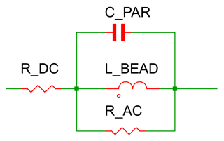
Figure 1: Ferrite Bead Equivalent Circuit
How should ferrite beads be used in gate driver applications?
Ferrite beads are most useful in a gate drive application when used to reduce ringing and noise on the gate node of the switch. Traditionally, resistors have been used to reduce this gate noise, but using a resistor means that a portion of the drive signal is also dissipated, slowing the switching speed and causing losses. Ferrite beads can be selected to remove noise without significantly affecting the drive signal, leaving the switching behavior of the power transistor unchanged. The scope captures below show a gate switching both without a ferrite bead, and with a ferrite bead between the gate and the output. Using a ferrite bead on the gate of the power switch is recommended to improve the reliability of the drive circuit, particularly when switching a noisy FET, for example a FET with fast rise time or a low internal gate resistance. Ferrite beads can be used in series with gate resistors to gain the most benefit, as shown in Figure 4, and should be placed as close to the FET as possible.
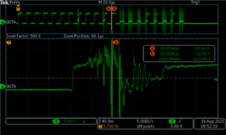
Figure 2: Gate Noise Without Ferrite Bead
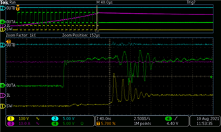
Figure 3: Gate Noise With Ferrite Bead
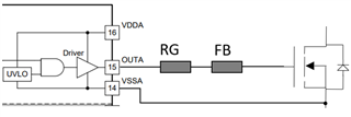
Figure 4: Ferrite Bead Placement
How should a ferrite bead be selected?
When selecting a ferrite bead for gate drive applications there are two major factors to take into consideration: the saturation current, and the impedance at the frequencies of interest.
The goal of a ferrite bead in these applications is to reduce gate noise. For this purpose, it is desirable to have minimum impedance at the driving frequency, and a high resistive impedance at the noise frequency. Generally, the noise will be around 100 MHz. Choosing an appropriate ferrite bead involves looking at the frequency versus impedance plot on the devices datasheet. This plot should include three lines, the overall impedance (Z), the inductive component of the impedance (X), and the resistive component of the impedance(R). A ferrite bead should be chosen such that the resistive component is maximized at the noise frequency to dissipate as much energy as possible, while the overall impedance at the switching frequency is minimized to prevent unwanted losses. An example plot from the MPZ1608S101 ferrite bead by TDK is shown in Figure 5. This ferrite bead works for many gate drive applications because it has very low impedance below 1 MHz at the switching frequency, but high impedance starting at 10 MHz and increasing all the way to 300 MHz.
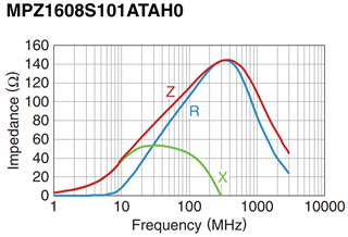
Figure 5: Example Ferrite Bead Impedance Plot from TDK MPZ1608 Datasheet
The second factor that must be taken into consideration is the saturation current. Ferrite bead performance depends significantly on saturation current, so it is good practice to select a ferrite bead with a saturation current at least twice the expected peak current, for example 3 A if the drive current is normally expected to be 1.5 A. As the saturation current is temperature dependent, make sure to take this into account when choosing a ferrite bead.
