This thread has been locked.

If you have a related question, please click the "Ask a related question" button in the top right corner. The newly created question will be automatically linked to this question.

TPSM82822: Stuck in 100% mode

Part Number: TPSM82822

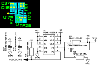
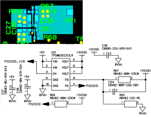
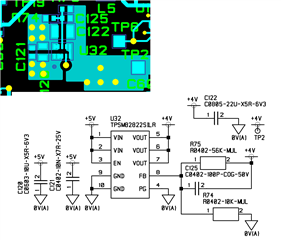
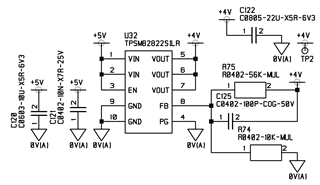
I am using the TPSM82822SILR in a new design. I use it to generate 1.9V, 3.3V and 4V. For the 4V supply I tried increasing the 100pF capacitor to 1.1nF. but it makes no difference

For all 3 supplies they are disabled when the input is below 2.4V as expected. Above 2.4V the supplies switch on, but the output voltage matches the input voltage so they are stuck in the 100% mode. The voltage on the FB pin does not regulate to 0.6V but follows the output in proportion to the divider. It goes well above 0.6V.

For example, the 1.9V regulator has just under 2.5V on the output when the input is 2.5V. All three designs are similar with only the divider ratio different.

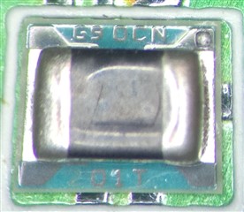
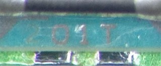
The package marking is GA so ibelieve the correct part is installed.

I would appreciate any help or suggestions as to why the part will not regulate but is stuck in 100% mode.

  • Hi Sean,

    I reviewed the schematic and could not find any issue. However, I would like to know the positioning of the input and output capacitors with respect to the IC. Is it possible to send us the layout?

    Do you meet the minimum Vin requirements as explained in 8.3.2 while designing? 

    What is the max load of the system?

    Can you share the Vin, Vout, Vfb, EN scope plots if possible?

    Regards,

    Febin

  • The 1.9V supply is supposed to come on first and enable the 3.3V supply as sequenced supplies for a TMS320F28355 DSP. The DSP's 1.9V supply has four 2.2uF caps distributed around the DSP but none directly on the 1.9V reg. I wound the supply up to 2.5V which is the abs max level for the 1.9V DSP rail. The output followed the supply up to 2.45V.

    I removed the 1.9V reg to protect the DSP and looked at the 4V0 rail. It has zero load and should be fully independent of the other rails. It's output also follows the supply. I wound it up to 4.5V.The output also goes up to nearly 4.5V. The FB pin goes beyond 0.6V with no sign of regulation.

  • I looked at the rails on the oscilloscope. They are flat. Vin = 4.9V, Vout = 4.87V. Vfb = 0.77V. These are for the 4.0V rail

  • Hi Sean,

    The layout looks good. I would like to confirm a few things first.

    - Please restart the system/ TPSM82822SILR. 

    - Please measure the resistance between Vin & Vout pins. If it is low impedance then the device is damaged.

    - Please swap with new ICs if it is already damaged and then retest.

    Regards,

    Febin

  • For all three regulators I did a test to see what would happen if I short circuited the upper resistor of the divider tying the FB to the output. In each case the the output went to 1.8V. Also for the 1.9V regulator the PG output went high enabling the 3.3V regulator.

    This leads me to believe that these are not the adjustable TPSM82822SILR parts but are in fact the fixed output TPSM828222SILR. However the device marking is G9 near pin 4/5. Near pin 6 there is a number 2.

    G92 would be correct for the TPSM828222SILR 1.8V part.

    How is the device marking shown on the package? is there a drawing?

  • Hi Sean,

    Let me confirm this internally and I will get back to you today. But let me clarify, have you tried new ICs from the same lot and is it the same always?

    Could you share the lot number? How many ICs have you tested so far?

    Regards,

    Febin

  • In silk screen on the pin 1 side of the package it says G9 OCN. On the other side it looks like  laser etched 2 followed by silk screen 01T.

    I had a subcontractor manufacture 20 off boards for me which I am testing prior to shipping to the end user. I  don't have the required setup here for removing and replacing these surface mount parts.

    The subcontractor has confirmed that their purchasing called up the correct parts but the devie supplier may have possibly had a mix up?

  • Hi Sean,

    It is very rare that such a mix up happens. Nevertheless, please provide a clear picture of the device marking from top so that we can ourselves verify if it is the right part or not.

    Please confirm once again:

    -all three modules on the same board have the same behavior? 

    -it can regulate at 1.8V and when Vin increases, output is simply following the input. But none of them are damaged.

    -All 20 boards have the same problem?

    Regards,

    Febin

  • This is the part. The top says G9 OCN. The bottom has a very faint 2 (Laser etched?) followed by 01T.

    I have tested two boards. 

    On one I have removed the 1.9V regulator to protect the DSP dfrom overvoltage destruction.

    What should be the 3.3V supply gives 1.8V when I short the upper resistor connecting Vfb to Vout over a range from 2.4 to 4.7V. The output rises to 1.9V at 5V.  For the 4.0V rail when I short Vfb t Vout it gives 1.8V Vout for Vin from 2.7 to 5V.

    On the 2nd board, with the 1.9V regulator working and Vfb shorted to Vout I see Vout = 1.8V for Vin in the range 2.4 to 3.3V. I cannot go above 3.3V because I do not want to overvoltage the DSP 3.3V rail.

    I am reluctant to test more boards becasue of the risk of damaging the DSP which would effectively scrap the boards.

  • I have just done a further test. For the 1.9V rail I removed the lower of the two resistors leaving Vfb connected to Vout through the 22k resistor. I reworked the 3.3V rail and 4.0V rail changing the values for the upper resistors R75 from 56k to 12k and R67 from 100k to 18k. In effect I have adjusted the potdowns to assume Vfb is 1.8V rather than 0.6V. My regulators now produce 1.85V, 3.3V and 4.08V which si good enough for my purposes. I shall rework the boards bases on these modifications.

    In my view that is fairly conclusive that the fixed 1.8V part has been fitted instead of the designed asjustable part.

    I would be grateful if you could confirm this is in line with the device markings.

  • Hi Sean,

    Thank you for all the details and sharing the pictures.

    It looks like the device is a fixed output version- TPSM828222SILR. There is a laser marked “2” left next to the “01T”.

    Please let me know if you need further help on this matter.

    Regards,

    Febin