This thread has been locked.

If you have a related question, please click the "Ask a related question" button in the top right corner. The newly created question will be automatically linked to this question.

LM60430: Schematic review and EMI filter design

Part Number: LM60430
Other Parts Discussed in Thread: LM43603

Dear *,

We are using LM60430D.

Vin= 12V to 24V

Vout= 5V

Iout_max= 3A

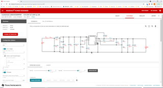
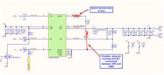
Please see the attached schematic if it looks good?

0574.Power Input.pdf

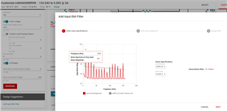
We also tried to add EMI filter in WEBENCH Power designer to our design https://webench.ti.com/power-designer/switching-regulator/customize/468

But we don't know how to select Line impedance in the EMI filter design tool ?

We want the CISPR25 CLASS5

Difference our schematic vs WBENCH schematic:

-we have 2x 10uf on input while WB has 1x10uf ( can modify the capacitance quantity in WB)

-we have 4x 47uf and 2x100nf on output while WB has 2x47uf and 1x100nf  ( can modify the capacitance quantity in WB)

- we have 2x150uf 10V tantalum on output

- we have 4x100uf 35V Aluminum Electrolytic on input ( can reduce to 2x 100uF)

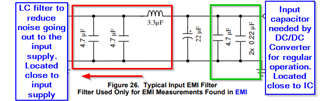
Please can you help to design input EMI filter with the WB tool?

Also we want to use the same 4.7uH ( ETQ-P4M4R7KFM) inductor for the filter if possible? or the 470nH CIGW252010GLR47MNE.

Best Regards,

David.

  • Hi,

    The schematic looks ok.  

    I see the webench link is for LM43603? 

    Can i confirm that you are using the commercial version of the part and not automotive? The reason why i ask is because CISPR25 is an automotive standard. 

    The automotive part runs only with 400kHz option. From the schematic i see that you are selecting the commercial part with 1MHz switching frequency. May i confirm this operating condition?

    In terms of reccomended filter, we have a guide in the datasheet in here:
    https://www.ti.com/lit/ds/symlink/lm60430.pdf?ts=1633104034604&ref_url=https%253A%252F%252Fwww.ti.com%252Fproduct%252FLM60430#page=23

    You may be able to use the 4.7uH inductor instead of 3.3uH on the datasheet. One thing that i would also recommend in your design is to add place holder for snubber or boot resistor in order to improve EMI

    Thanks

    -Arief

  • Hi Arief,

    1) Pleas see screenshot, this is the link and it is for LM60430DRPKR

    2) we are using non automotive part LM60430DRPKR 1MHz 

    Yes i know that CISPR25 for automotive, but this standard has the lowest limit, that can be selected within WEBENCH.

    3) can you tell how is the filter cut off frequency selected? is 1 or 2 decades bellow the first frequency noise spike?

    in WEBENCH when i click add EMI filter i get that the first spike is at 1MHz

    Do we choose 100kHz or 10kHz for the filter cut-off frequency?

    4) I missed the EMI filter in the datasheet. I will look in to that. 

    But the WEBENCH i get Lf=470nH and Cf=10uF can you please comment that  or is there an error in WEBWNCH?

    5) Please can you tell where to add place holders for snubber and boot resistor and what values?( can you please sketch on our schematic)

    6) General question regarding EMI filter.

    5a)I'm going through a lot of EMI filter material and i see that they approach to split the inductor value in halve on VIN and GND lin, do you recommend this approach?

    5b) also in DS page 24 the cf 2x4.7uF is on the left side of inductor ( VIN side), but a lot of EMI filter have the cf cap have on the right side of inductor ( Regulator input side)

    Like in this video:   https://www.youtube.com/watch?v=UOCsqNtRL74

    Can you please comment this? or is this filter in the video for the input EMI and not for the EMI that is generated by the DCDC?

    Best Regards,

    David.

  • Hi,

    3) It depends how many dB of attenuation that you would like, considering an LC filter, 1 decade below will get you 40dB attenuation and 2 decade below will get you roughly 80 dB attenuation. You can refer to this app note for design https://www.ti.com/lit/an/snva489c/snva489c.pdf

    You can use 10kHz for more conservative design. 

    4) I would recommend the EMI filter in the datasheet since we tested using those values. 

    5) 

    6a) Do you mean using a common mode choke? If yes, i think it's good if you have a common mode noise but you still need a regular LC filter to reduce the differential noise at fundamental switching frequency of 1MHz.  I never tried to split the inductor since i don't have the chassis to connect to. Normally we only use the regular LC filter as primary filter. 

    6b)  In terms of the capacitor. Here is the description of the purpose of those capacitors

    You can also refer to our EVM to see where the location of the input filter and the values being used. 

    https://www.ti.com/lit/ug/snvu693/snvu693.pdf?ts=1633450648266&ref_url=https%253A%252F%252Fwww.ti.com%252Fproduct%252FLM60430-Q1

    Thanks

    -Arief

  • Hi Arief,

    thank you for the data, i will go through it. ( But your filter is designed for 400kHz and we have 1MHz)

    Is it possible that you comment the filter that designed the WEBWNCh?

    One questions tough: we have two  LM60430DRPKR  that have the common Vin but one is creating 5V and other 9V.

    Can we have one LC filter or do we need to have separate?

    Or can i calculate the worst case input impedance of two converters and then calculate the parallel input impedance and design filter with this value?

    -------------------------------------------------------------------------------------------------------------

    Calculation:

    So i calculated the smallest impedance for both cases estimate -> Zin=(VIN*VIN*eff)/(Pout) 

    12Vin -> 5Vout (iotmax_3A) (eff=94%) -> Zin-DCDC=9Ohm

    12Vin -> 9Vout (iotmax_0.25A) (eff=94%) -> Zin-DCDC=45Ohm

    Parallel= 7.5Ohm

    The switcher used is 1MHZ, -> so i would go for f_cutoff= 100kHz

    and the output impedance of the filter i would like to be 10 lower then 7.5Ohm = 750mOhm (middlebrook stability criteria) 

    and then i would select the L=1uH and C=4.7uF effective ( use 10uF (50V) cap  that has ~ 4.7uF at 12V)

    f_cutoff  actual = 1/(2*pi*sqrt(LC))= 73.45kHz

    and then i would spilt the 1uH into 2x 470nH -> fc= 75kHz

    Then select damping cap to bin min 5x larger than Cf (4.7 *5)--> Cd_min= 22uF electrolytic so that we don't need external damping resistor

    So i would go with 2x 22uF with ESR ~ 900mOhm -> Q=1=(1/rd)*(sqrt(L/C)) -> rd = parallel of 2 22uF = 450mOhm

    Q=(1/0.45)*(sqrt(940nH/4.7uF)) = 0.99

    -------------------------------------------------------------------------------------------------------------

    Please can you comment the calculation, is this a way to go?

    Best Regards,
    David.

  • Hi,

    I believe you can just use one LC filter for both converter. 

    Yes the calculation makes sense. It seems that you want to use the splitting the 1uH method per video.

    But yes with 1uH that will give you a cutoff frequency of 100kHz and attenuate roughly 40 dB of the 1MHz signal. 

    Thanks

    -Arief