Team,
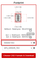
It seems that the Ultralibrarian CAD file (detailed view) for RDH footprint (see below link) does not include all dimensions from our drawing provided at page 28/29 of the datasheet SLVSFS5:
https://www.ti.com/product/TPSM63603?keyMatch=PTPSM63603RDHR&tisearch=search-everything&usecase=OPN#cad-cae-symbols
Here are some feedback/questions I received:
The footprint file does not visually match the drawing from the datasheet:
-For pins 1,8,14 and 21, it would also be helpful to know the exact position in relation to other reference surfaces.
-where are pins 27 to 30 are located in relation to the symmetry axis or other reference surfaces?
-Is there an upated PCB footpring file that contains all dimensions from the TPSM63603 datasheet drawing?
-Will there be a 3D model for this RDH package?
Thanks in advance!
A.