This thread has been locked.

If you have a related question, please click the "Ask a related question" button in the top right corner. The newly created question will be automatically linked to this question.

LM61460-Q1: PFM threshold to FPWM when Vin=12V, Vout = 3.3V and Iout =3.5A, Fsw = 400kHz

Part Number: LM61460-Q1
Other Parts Discussed in Thread: LM61460EVM, , LM61460, LM61440

Hi Team,

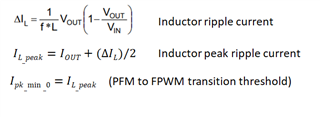
I want to know the threshold when PFM mode enter in FPWM mode when we set auto-mode. Out condition is 12Vin, 3.3Vout and 3.5AIout. (Fsw = 400k)

How can we calculate the minimum peak inductor current value that let PFM node to FPWM mode? I reviewed the below thread, but still have no idea.

Can you help calculate the threshold value for me step by step based on above condition? Thanks.

https://e2e.ti.com/support/power-management-group/power-management/f/power-management-forum/897988/lm61460-q1-lm61460-q1-pfm-mode?tisearch=e2e-sitesearch&keymatch=LM61460%20PWM%20thrshold#

Roy

  • Hi Roy,

    Instead of calculations, the best way to go about evaluating is by testing on the EVM.

    I would suggest taking the existing LM61460EVM and configure it for 3.3Vout. 

    Then scaling and progressively loading the device with current from 0A to 3.5A and probing SW node should clearly show when the transition occurs.

    At PFM, the device will have some parasitic ringing on the SW node, but as current is increased the device will eventually enter FPWM mode of which the SW node waveform will be constantly square wave.

    Regards,

    Jimmy

  • Hi Jimmy,

    I wish I can do the real measurement to identify the threshold value, but my customer need the calculation and provide to their end customer. 

    So we need calculation for them even though there is large difference.

    Roy

  • Hi Roy,

    I will need to check with the systems and designer.

    There is nothing mentioned in the datasheet and I am not aware of how it is calculated.

    Let me get back to you on this.

    Regards,

    Jimmy

  • Hi Roy,

    I am still in communication with designer on this.

    There currently is no equation readily available, but I hope we can come up with something and provide you with more information.

    Will keep you posted when there is an update.

    Regards,

    Jimmy

  • Hi Roy,

    Theoretically we can imagine that the moment the peak inductor ripple current passes over the minimum peak command in Auto Mode is the point of transition from PFM to FPWM. The point of transition depends on the duty cycle, frequency, inductance and DC load current. 

    In this case, we can come up with an equation as shown below.

    The LM61460-Q1 datasheet specs the I_pk_min_0 to be 25% of IOUT. In this case the peak current command would be around 0.25*6A = 1.5A.

    The load current in the customer application will have a peak and valley inductor current.  

    Again this is a very crude way of calculating and customer should expect a large difference.

    Regards,

    Jimmy

  • Hi Jimmy,

    Can you let me know the definition of pulse duration? I think it's the duty cycle high level duration, is it correct? In my condition, Fsw = 400kHz, duty cycle = 3.3/12. The duty cycle high level duration is 1/400000*3.3/12 = 0.6875us.

    The relationship between I_pk_min_0 and Iout is not list in datasheet. 

    I want to know the 6A is the constant parameter? Due to my condition, Iout(max) = 3.5A only. Do I need modify the formula to 0.25*3.5A?

    In this case the peak current command would be around 0.25*6A = 1.5A.

    Last image you attached, Iout should be 3.5A*0.25? We can accept large difference, but I need reasonable formula to convince customer. 

    Regards,

    Roy

  • Hi Roy,

    The crude equation is set by the device current rating. In the case for using the LM61460 then device current rating is 6A and the equation will take 25% of that as the peak current command. If you are using a LM61440 device, then the device current rating is 4A.

    Iout_max is your application and load current. Remember that when you will load current there will be inductor ripple current ontop of the DC load current.

    In the case of 3.5A, your application will be well over the transition point and will be in FPWM. 

    However as your DC load current reduces, it will get to a point where the load current results in a inductor peak ripple current that is below the peak current command. This is the point when the device will transition back to PFM and the switching frequency will be significantly reduced.

    Regards,

    Jimmy