This thread has been locked.

If you have a related question, please click the "Ask a related question" button in the top right corner. The newly created question will be automatically linked to this question.

TPS65400-Q1: Compensation circuit caluculation

Part Number: TPS65400-Q1

Hello experts,

I have question about Compensation Calculation.

1. Could you tell me each unit for items(F, R, C, Gm, Gmps) in equation?
2. In Figure 17, there is not Cff. C1 is Cff?


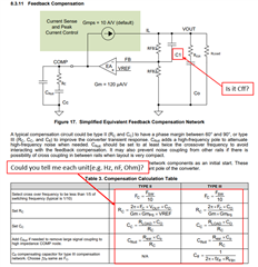
3. From user's guide Figure 2-1, the compensation circuit is not match with datasheet Figure 17.
Could you tell me how to decide compensation circuit?
If there is example of calculation, it's helpful.

Thanks and best regards,
Ryo Akashi

  • Hi, Ryo 

    1. Fc is Hz, R is ohm, C is F, Gm and Gmps are A/V. 

    2. Yes, the C1 is Cff. 

    3. The compensation circuit is determined by loop bandwidth fc, which means compensation circuit is different when setting different fc. 

    You should set the fc first, then do the calculation based on the equations. 

    There is a calculator for your reference. 

    TPS65400_Design_Calculator.xlsx