This thread has been locked.

If you have a related question, please click the "Ask a related question" button in the top right corner. The newly created question will be automatically linked to this question.

LM25085: Incorrect design in Webench

Part Number: LM25085
Other Parts Discussed in Thread: LMR50410, LMR36510,

Hi,

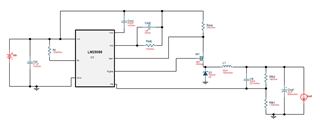
I am a big fan of Webench and have used it for many SMPS designs. My latest design however, utilising the LM25085 seems to have some issues.

Setting Vin to 15 - 36V, Vout to 13.5V @ 1.2A results in the attached design.


Note: Rfb1 is 1.02k, Rfb2 is 10k and Radj is 732 Ohms.

I built this as per the Webench design and the output voltage and the current limits are incorrect. The datasheet provides the formulas for Vout and Icl which match what I have built.

Designed / desired Vout is 13.5V, actual is 9.7V.

Designed / desired Icl is 1.2A, actual is 2.9A.


Regards,

Andras

  • Hi Andras,

    Please use the LM25085 quickstart calculator to verify your design: https://www.ti.com/tool/LM25085-5085QUICK-CALC. Is the design operating stably based on the ripple generated by the output cap ESR? I see the FB divider is setup for a 13.5V output (based on the 1.25V FB voltage). Also, the current limit is set at 2.92A peak (= 40uA*732Ω/10mΩ), most likley to (1) provide some margin over the full-load current rating, and (2) to accommodate the inductor ripple current, load transients, etc.

    Note that we have converters (with integrated FETs) that provide a smaller solution size and an easier design for this ~1A application. See the LMR50410 36V, 1A converter as an example. Or for higher Vin rating, consider the LMR36510 65V, 1A converter.

    Regards,

    Tim

  • I see what my problem was, I am using the LM25085A which I didn't realise is a different part with a different reference voltage.

  • Thanks, Andras. Yes, the "A" version has a 0.9V FB threshold.