This thread has been locked.

If you have a related question, please click the "Ask a related question" button in the top right corner. The newly created question will be automatically linked to this question.

UC1842A: Duty Cycle

Part Number: UC1842A

Hi,

Good Day. I have a customer who is working with UC1842A. Please see below the query of the customer for your reference. Thank you very much.

We are working on a Flyback transformer with UC1842A where two output conditions shall be satisfied.

We need 30V-6A where load impedance is low, and 300V-300mA where load impedance is high.

We designed a custom transformer with N21=1 and in order to obtain both voltages varying the duty cycle.

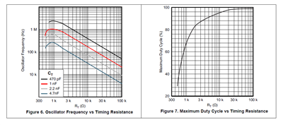
However, the duty cycle control method is not well described in the datasheet and the AN SLUP068 does not help with the application.

Can you please share a more accurate circuit description on duty cycle control on this device?

Best Regards,

Ray Vincent

  • Hi Ray

    UC1842A uses current mode control for flyback converter. If you want to know more info about current mode control. You can refer to this application note:

    www.ti.com.cn/.../slua119.pdf

  • Hi Jerry,

    Good Day. Please see below the response of our customer to your reply. Thank you very much.

    I would like to ask how can I set the duty cycle on UC1842x devices. There is an approximate circuit on the datasheet but no information is given about it, just put on the document. I would like to pass from 25% duty to 75% duty on my Flyback controller, otherwise I can accept the converter to deliberately change the duty cycle but maximum shall be 75%, which is impossible with RT>5 KOhm (as datasheet suggests)

    Best Regards,

    Ray Vincent

  • Hi Ray 

    Let me understand your question first, the duty cycle of your flyback converter varies between 25% and 75%. So you want to set the maximum value of duty cycle 75%. Is it right?

  • Hi Jerry,

    Good Day. Please see below the response of our customer to your question. Thank you very much.

    Your Question:

    "The duty cycle of your flyback converter varies between 25% and 75%. So you want to set the maximum value of duty cycle 75%. Is it right?"

    Customer Response:

    This can be a solution. However, on the older datasheet there was a graph with a duty vs RT plot where 75% max duty corresponds to 1.2 KOhm while in the new datasheet RT value is recommended bigger than 5 KOhm.

    It seems that there is the possibility to lower the max duty cycle but there is no information on how to do that.

    Can you please explain this?

    Best Regards,

    Ray Vincent

  • Hi Ray

    In this graph, there is a relationship between fsw and RT, CT. You can use this graph to select an suitable value of RT/CT and satisfy the constraints of maximum duty cycle. In TI's proposal, this value can obtain a accurate fsw and maximum duty cycle. But if you select a value out of the recommended range, the IC can work normally too.