This thread has been locked.

If you have a related question, please click the "Ask a related question" button in the top right corner. The newly created question will be automatically linked to this question.

LM5155: Oscillation does not stop under low temperature

Part Number: LM5155

I designed a flyback converter using the LM5155.
The voltage generated on the secondary side of the flyback transformer is fed back to the FB pin to maintain the target voltage.

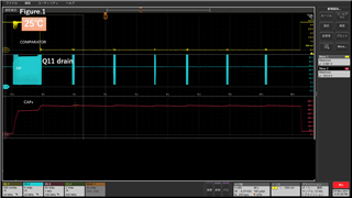
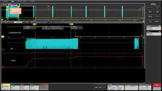
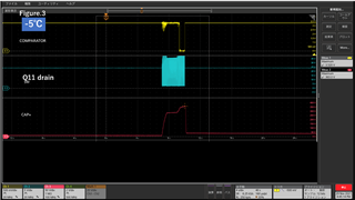
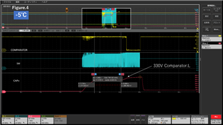
The converter operated normally at room temperature, but when evaluated in  -5°C condition, the oscillation at the GATE pin did not stop even after the target voltage was reached.


This problem is also reproduced when the LM5155 is cooled locally.

Are there any considerations that should be made to maintain the target voltage at low temperatures?

  • Hello, 

    Thanks for reaching out. Could you please share the following details: 

    • schematic of your flyback 
    • specs of your design (Vin, Vout, switching frequency, Iout)
    • scope plots of Vout, gate voltage, switch node

    At cold temperature, oscillations on the Vout might be caused by the use of electrolytic caps, which type of capacitors are you using at the output? I'm looking forward to hearing from you soon.

    Kind regards, 

    EM 

  • Hi EM,

    Ide-san is our customer and he would like to share information which you requested including confidential schematic.

    But there is no "Send a private message" option when I click your icon.

    Could you please provide any way that how to share confidential information to you? 

    Best regards,

    Shota Mago

  • Hello Mago-san, 

    Thanks for sharing this information with me. You can either post this information in the internal E2E forum or reach out for me via email, as you prefer, I also sent you a friendship request in the E2E. As we will discuss this issue privately, I will close this thread. 

    Kind regards, 

    EM 

  • Hi EM-san,

    I sent the schematic to you via private message. Please continue application support of LM5155 for Ide-san.

    Best regards,

    Shota Mago

  • Hi EM-san,

    Could you please provide your comment on this thread once you've reviewed customer's schematic?

    Best regards,

    Shota Mago

  • Hello Mago-san, 

    Thanks for sharing the schematic. As first thing, I would suggest to add a slope compensation resistor on the CS pin (R87, 1k for example). In addition, I have two questions: can you please share what type of capacitor C47, C48, C49 and C50 are (e.g ceramic or electrolytic)? In addition, can you share with me the scope plot of this oscillation that was seen at cold temperature (best would be to check the switch node, the gate, the Vout and CS pin)? I'm looking forward to your answer. 

    Kind regards, 
    EM

  • Hi EM,

    Thanks for your reply.

    C47,C48,C49 and C50 are ceramic capacitor(GRM55DR7LW224KW01;MURATA).

    We monitored the comparator output indicating that the target voltage was reached, the drain voltage of the switching FET, Q11, and the output voltage.
    Unfortunately, when we tried to monitor CS, the LM5155 could not operate stably.

    Figure.1 25°C
    Figure.2 Enlarged view of FIgure.1
    Figure.3 -5°C
    Figure.4 Enlarged view of FIgure.3

    The output of the comparator switches to "L" when it reaches the target voltage (330V).
    At room temperature, the GATE stops after about 250ms when the target voltage is reached.

    However, at -5°C, the GATE output continues for about 800ms after reaching the target voltage, and Vout is higher than the target.


    For safety reasons, Vout is monitored by the CPU. When the voltage exceeds the target voltage by about 30V, the circuit is configured to automatically discharge Vout to the resistor.

    If you need more detailed plots of the oscillations, please let me know.

    Best regards,

    Katsuya Ide

  • Hello, 

    Thanks for your feedback. It seems like the capacitor is getting quickly discharged and the comparator is then reacting. Did you try to perform this test only with the capacitor connected but no additional load? 

    Kind regards, 

    EM

  • Hi EM,

    Thanks for your reply.

    Yes.

    The discharge of the capacitor is controlled by a high voltage switching device. At low temperature, when the CPU senses an overcharge, its switching device is turned on and the charge of the capacitor is discharged, which causes the comparator to react. In other words, when the voltage was being boosted, the discharge resistor (load) was not connected to the converter.

    Regarding the LM5155, is there any possibility that the response of the FB pin is slowed down at low temperatures?

    Best regards,

    Katsuya Ide

  • Hello Katsuya-san, 

    Thanks for your feedback. I would not expect the controller to misbehave at this temperature, especially because -5 C does not sound excessively cold. Do you have the possibility to test this circuit without the load resistor to discharge the cap? To see if the capacitor can be fully charger without issues at cold temperature? Which type of device in particular is connecting and disconnecting the load resistor? 

    Kind regards,
    EM