This thread has been locked.

If you have a related question, please click the "Ask a related question" button in the top right corner. The newly created question will be automatically linked to this question.

LMZ34002: Load Step Simulation Issues - Undershoot does not recover

Part Number: LMZ34002

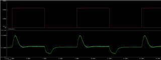
I have been running simulations in PSPICE for the LMZ34002. When I modified the steady state design to incorporate a load step, I am seeing that the when the step occurs, an overshoot happens and then settles back to -15V. When the step goes away, you'll see the undershoot, but it never recovers like how the overshoot recovers unless it needs much more time than I set at 1ms for the load step pulse.

I took a look at the webench design and it seems much more reasonable.

Input: 25.2V-30.8V

Output: -15V

Iout: 0.3A

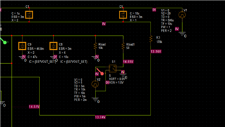
Below are screenshots of my simulation design and waveform. I'm using a switched resistor load. It initially has a 10k load for 1.5mA, and then a switched Rload of 50ohms for 0.3A. Any ideas? I'm looking to get better regulation around +/-250mV for a 0.3A, looks like the only way to achieve that would be more bulk capacitance? Would you agree?

  • Hello,

    As you mentioned, try extending the time that the load step is applied and observe how that changes the response. I expect that higher output capacitance will be required to achieve your desired load transient performance. 

    What is the steady state output voltage that you are simulating without the load step?

    Regards,

    Harrison Overturf 

  • I figured out the issue. I ran a 12V input with -5V output with the conditions listed in the Characteristic tables in the datasheet and the results were no aligning with what was listed in the tables for transient response. I figured out that the simulation doesn't include the 2.2uF cap between VIN and VOUT. Added it in, and got the same values for 12V input and -5V output as in the tables.

    Reran my simulation for 28V and -15V output with that 2.2uF cap, and it's working as expected.