This thread has been locked.

If you have a related question, please click the "Ask a related question" button in the top right corner. The newly created question will be automatically linked to this question.

BQ24171: Charging stop under low temperature

Part Number: BQ24171
Other Parts Discussed in Thread: BQ40Z50-R2, BQ40Z50, EV2400

Hi team,

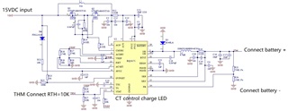
The customer use BQ24171 as a charger to charge a battery, battery use BQ40Z50-R2 as management IC. charger output 12.6V, the battery rated voltage is 12.6V.

There is a phenomenon that the charging LED will off (STAT pin control) when charging last over 8 hours and under 10 degree environmental temperature, when environmental temperature above 10 degree, the charging LED will still on and give out a right charging status.  when LED off, the charging stop at same time.

The LED will still off(charging stop) even temperature rise up to 25 degree. charger or battery can not wake up by themselves unless battery re-plug.

Issues:

1. Why the charging LED off(charging stop) only happen with environmental temperature below 10 degree ? 

2. Which IC , BQ24171 or BQ40Z50 cause this LED off under 10 degree temperature?

3. Why LED off  phenomenon happen after charging time over 7 hours? why not happen in a shorter time? 

4. Could you recommend a tool to analyze this issue?

NOTE:

The BQ24171's TS pin configuration : RT1=2.2K, RT2=6.8K, RTH=10K.

The TS voltage is still below 2.32V, Vref=3.3V under low temperature environment.

The voltage of battery is about 11.7-12.1V after LED off (charging stop), full charged battery voltage should be 12.6V.

Could you help check this case? Thanks.

Best Regards,

Cherry

  • Dear Cherry,

    Can you please confirm if the STAT pin is off, or if it is blinking? What is the input voltage used here? Can you please send a schematic?

    Thanks,

    Mike Emanuel

  • Hi Mike,

    Thanks for your support here! The charge voltage is 12.6V, battery is 3S2P, rated voltage is 12.6V.

    The BQ24171 charge circuit, Charge led control circuit _1, Charge led control circuit_2, and BQ40Z50-R2 circuit are as follows:

    Thanks and Best Regards,

    Cherry

  • Dear Cherry,

    Can you please probe the input voltage, STAT pin, charging current, and SW pin during normal and abnormal operation?

    Thanks,

    Mike Emanuel

  • Hi Dear Mike,

    What do you mean about output voltage? 

    There is about 11.9V with battery connection when LED off (stop charging) and 12.5V without battery connection under 5 degree.

    The current is 0 when LED off. normal charging current is about 0.5A under 5 degree.

    Is there any problem found in BQ24171 and BQ40Z50 circuit?

    Thanks and Best Regards,

    Cherry

  • Dear Cherry,

    Can you confirm what thermistor is being used? If you are using a 103AT, the resistance at 5C is 22.05 kOhm. With a 6.8 kOhm lower resistor, the lower equivalent resistor is 5.20 kOhm. With a 2.2 kOhm pullup, the TS pin becomes 70.26% of VREF. This is within the range of suspending charge. Please use the calculation tools to program the desired temperature range.

    https://www.ti.com/lit/zip/sluc244

    The issue may be related to the TTC pin. Correct me if I am wrong, but the TTC capacitance looks like it is 100 nF. This places the TTC timer at 100nF *5.6min/nF (typical) or 560 minutes or 9.33 hours. If you would like to disable termination and the safety timer pull TTC to AGND. If you would like to disable just the safety timer but allow charge termination, pull TTC to VREF.

    However to confirm this I would need to see the following waveforms. Can you please probe the battery voltage, STAT pin, charging current, and SW pin during normal and abnormal operation (all on the same plot)?

    Thanks,

    Mike Emanuel

    Please click "Resolved" if this answered your question.

  • Hi Dear Mike,

    Thanks for your support!

    The thermistor type is 103JT-V-045, the resistance is about 22.3K at 5C. Is it ok for their 5C low temperature application? Could you help check it?

    TTC pin may a key point needed to verify.

    If the issue can be resolved by TTC pin pull to VREF or pull GND, there will be no further question. 

    Here's an additional question: no all battery LED turn off during charging at 5C,  some charging LED still on and indicate charging is full.

    but base on battery capacity, battery need 7 hours to charge full with full current, if there is only half current charging at 5C, in theory, a discharged battery need  about 14 hours to charge full with half current, but base on their design,  the charging will terminal when reach 560min, what's reason make this phenomenon(charging LED on) happen?

    Thanks and Best Regards,

    Cherry

  • Dear Cherry,

    This thermistor and resistor combination puts TS at 70.3% of VREF at 5 C. This is within the range of the specification of suspending charge. Please adjust the bias resistors accordingly using the calculation tools I provided.

    I am still unclear on the behavior of the STAT pin and the LED. Is it blinking at 0.5 Hz or is it completely off? This behavior will assist in the debugging.

    The safety timer exists as a safety backup to prevent from charging for too long. The maximum time for the safety timer is 10 hours as shown in the datasheet. Again, if you would like to disable termination and the safety timer pull TTC to AGND. If you would like to disable just the safety timer but allow charge termination, pull TTC to VREF.

    Thanks,

    Mike Emanuel

    Please click "Resolved" if this answered your question.

  • Hi Dear Mike,

    The customer are doing the TTC safety timer test.

    Here are some questions about charging LED about BLINK status:

    1. Whether the charger entry Charge suspend status when TTC safety time over?

    2. How to distinguish with Charge suspend / Battery overvoltage/ Input overvoltage when STAT output BLINK?

    Input overvoltage is charger output voltage?

    Battery overvoltage is battery output voltage?

    3. Do they need a EV2400 to learn battery registor status? 

    Thanks and Best Regards,

    Cherry

  • Dear Cherry,

    1. When the safety timer expires it is considered a timer fault; charge will stop and the STAT pin will blink.

    2. The STAT output alone will not tell you which of the five (charge suspend, input overvoltage, battery overvoltage, timer fault, and battery absent) is happening. In testing, you can realize these faults by observing the circuit behavior. Input overvoltage is determined by the voltage on the OVPSET pin and battery overvoltage is discussed in Section 9.3.17. Charge suspend can be observed by the TS pin voltage.

    3. This is a stand-alone part and there are no registers so the EV2400 is not required.

    Thanks,

    Mike Emanuel

    Please click "Resolved" if this answered your question.

  • Dear Mike,

    Thanks again for your support!

    The customer also would like to know if there is a overvoltage occur, how to judge this voltage come from? from charger side or battery side?

    Their battery is a smart battery and has SM signal output, can they use EV2400 to learn the battery inside information to remove battery side possible factor?

    Thanks and Best Regards,

    Cherry

  • Dear Cherry,

    The OVPSET pin is specifically used to monitor input overvoltage and input undervoltage.

    I am confused as to what you are asking, however there is Battery Overvoltage Protection, see Section 9.3.17.

    Thanks,

    Mike Emanuel

    Please click "Resolved" if this answered your question.