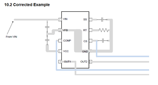
In the data sheet for the LM5030 100-V Push-Pull Current Mode PWM Controller, November 2015 edition, Figure 14 is a partial PCB layout example -

In the PCB layout example, VFB is grounded (which takes the error amplifier out of the circuit) and the COMP input is used to control the PWM. This is an inversion of the VFB input, which is suited for optical isolator feedback. This configuration can also be used to force the device into a near 50% push-pull duty cycle.
The example also indicates a DC bypass capacitor from Vin to the VFB pin, which is ground, so that works, if Vfb is grounded. If not (as in a voltage mode control application), ground must be wrapped around the IC or vias must be used to exit the trap, as indicated in the example.
The problem with the example is that a capacitor is shown tied from the Vcc output (which is regulated a 7.7V in this case) back to Vin, as opposed to VFB, which is ground. This is not indicated in the schematic and it would likely offend the internal voltage regulator, which also seems twitchy when it comes to decoupling and stability.
You might want to fix this error.