Other Parts Discussed in Thread: , TPS2595, BQ29209, LM5060-Q1, TPS25940, BQ29209-Q1
Hello E2E team,
Our customer needs your expertise in using the TPS25946 eFuse. Please help us answer the questions below about the device.
1. In Fig. 9.3, R5 and D1 (components needed for bidirectional current) connect pin OUT to pin IN. What is the PCB layout recommendation for R5 and D1? Can I put them far from the efuse?
2. Is Cout a required capacitor? Is it optional?
3.Fig 10.1 shows D3 and D4 for optional protection. Can D3 be the same part as D1? How about D4? Is D4 supposed to be the same part as the series diode with the resistor in Fig. 9.3? I am confused because the datasheet doesn't clarify these protection components. I am more confused since the evaluation board (TPS25946EVM) does not show these D3 and D4 (from Fig. 10.1).
4. If I do not need OVLO function, I can connect this to ground right?
5. If I do not need pin 3 and pin 4, I can leave them floating right?
6. Will there be an automotive rating version for TPS25946? When will it come? I am in need of a power switch that can handle bidirectional current in an automotive setting. And it seems like only this efuse can handle bidirectional current right now. Please share power switches that can also do bidirectional current.
7. Is TPS25946 the actualization of "Achieve Bidirectional Control and Protection Through Back-to-Back Connected eFuse Devices" Application report?
8. "Achieve Bidirectional Control and Protection Through Back-to-Back Connected eFuse Devices" Application report shows the use of TPS2595. However, the TPS2595 datasheet does not explicitly mention anything about bidirectional current capability when 2 efuses are used together. Does this mean 2 same units of ANY Texas Instruments efuses can be used for bidirectional current as long as it follows the "back-to-back" configuration?
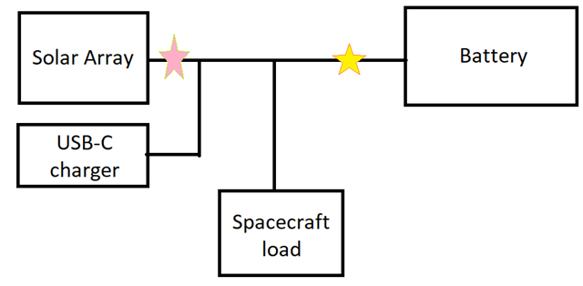
9.In the figure below, the USB charger will be used to charge the battery module before rocket launch. After rocket launch, only the solar panels will charge the battery module. In space, the battery module will source power towards the spacecraft load for science missions. The yellow star indicates the location of the bidirectional efuse. As you can see, power flows both ways inside the efuse. My question is: should pin IN or should pin OUT be connected to battery module? My hypothesis is I would connect pin IN to the battery module since overcurrent protection only goes to the forward direction. What do you think? Do you think pin IN is better to connect to the battery module or should it be pin IN? I am confused since the application report and the datasheet are kinda not consistent with each other.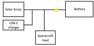
Thank you for the assistance.
Regards,
Carlo