This thread has been locked.

If you have a related question, please click the "Ask a related question" button in the top right corner. The newly created question will be automatically linked to this question.

TPS548B28EVM: Thermal question of TPS548B28

Part Number: TPS548B28EVM

Hi Team,

I am testing thermal capability on EVM  Iout=13A,vout=5V 600KHz, room temperature=22.3°C

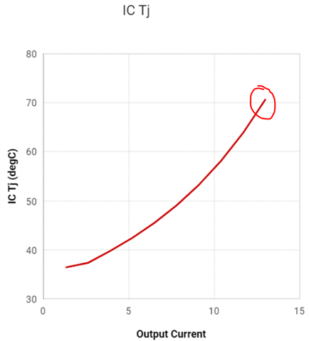
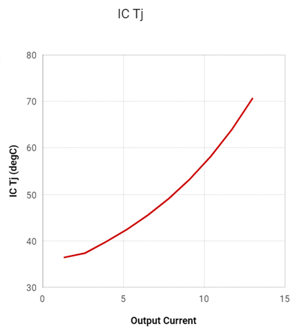
 I know “TJ = TA + (Thermal resistance × Power)”, and I used webench to get the power loss (2.257 W) and Tj. However the calculated and simulated Tj is only around 70°C

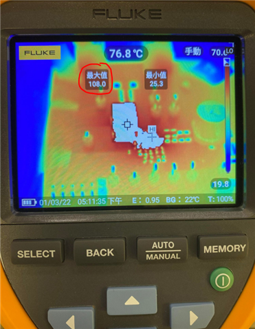
which is much lower than the top temperature (108 °C) I sensed with IR imager and it doesn't make sense.

1.Why would estimate Junction temperature is lower than top temp I measured, did I miss something? should I see ambient temperature as room temperature?  

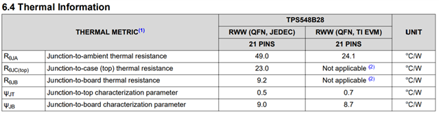
2.Why the junction to ambient thermal resistance is different between JEDEC and EVM? 


Regards,

Fred

  • Hi Fred,

    Our US team will reply you tomorrow.

  • Hi 

    I've updated my question above, please check.

    Thanks

  • Hello Fred,

    1. That is expected. The case temperature is defined as the hottest temperature on the top of the device. RθJA is a variable function of the package, design and layout of the PCB on which the part is mounted. In effect, the board acts as a heat sink.
      Yes, view ambient temperature as room temperature. The ambient temperature might increase a few degrees due to the heat dissipated from device.
    2. The values are different because the boards are different. A change in the design or configuration of the test board changes the efficiency of the heat sink and therefore the measured results.

    I've also attached two Application Reports in which I believe will be helpful in regards to thermal measurements.

    Regards,
    Alejandro

    slua844b.pdf6428.spra953c.pdf

  • Hi  team,

    Thanks

    1. my point is, I can use top case temperature and ΨJT to get junction temperature as well, and it will be like 110C, which is way more larger than the Tj (70C) I calculated with Ta and RθJA .

    and I know the fact is junction temperature will always be higher than top case temp (108C). However Wenbench show the Tj is only close to the 70C, so I'm confused.

    Which one should I believe? 110C or 70C

     2.  Does below description means ambient temp has its own definition, we can't just use room temperature?

    Regards,

    Fred

  • Hi Fred

        Just to be sure - can you please confirm that the load current of 13A is accurate? Also, can we rule out any calibration issues with the thermal camera?

    Regards,

    Gerold

  • Yes, I confirm I use 13A and it's accurate, and I don't think IR imager could have any problem that will affect so much (70C to 110C)?

    is webench Tj analysis accurate? what's equation is it base on?

  • Hi Fred,

    The WEBENCH analysis is more accurate. For example, see Thermal Performance of EVM on datasheet Section 10.2.1. The EVM at 20A measures only 88°C.

    Regards,
    Alejandro

  • Hi team,

    Thanks for the feedback, actually this is an qualification for HPE, so might be extra support

    1.So you mean my measurement is not accurate, any Idea why my IR imager sense overhigh temperature?

    2.  What does "2.54cm to the horizontal means"?  does this mean it's not  recommended  to use room temperature?

  • Hi Fred,

    1. Multiple factors can influence the readings. Here are a few:
      • I would recommend to capture the thermal image directly above (parallel to the board). Notice how the image is a bit slanted and not directly placed above. Placing the IR camera in a better position might help with the readings.
      • Be sure to correct the reading of the emissivity of the surface being investigated. I have a suspicion that the reading is also getting influenced from the high polished soldered pads of inductor. Low emissivity surface will act like a mirror. Instead of measuring the temperature itself, your camera will detect reflected temperature as well.
      • For low emissivity surfaces, apply black insulating tape, spray paint, black water-based stylus pen, etc. to help with measurements.
    2. It is recommended to use ambient temperature BUT the ambient temperature readings will have been influence due to the radiated heat. Therefore, the actual ambient temperature will equal the ambient plus radiated heat.
      The 2.54cm is a guideline on how to measure the actual ambient temperature after being influenced from the radiated heat of device/PCB.

    Regards,
    Alejandro