This thread has been locked.

If you have a related question, please click the "Ask a related question" button in the top right corner. The newly created question will be automatically linked to this question.

LP8733: Connecting EN pin and PGOOD pin

Part Number: LP8733
Other Parts Discussed in Thread: AM6442, TPS745,

Our customer is designing a prototype board with the AM6442 SR1.0 and powering the AM6442 with the LP873364.

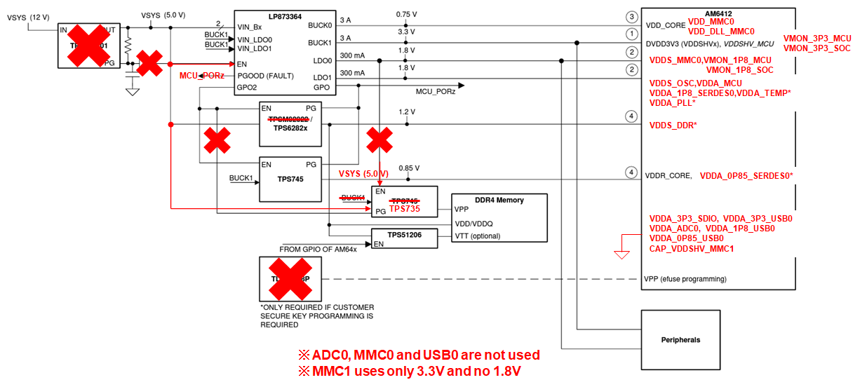
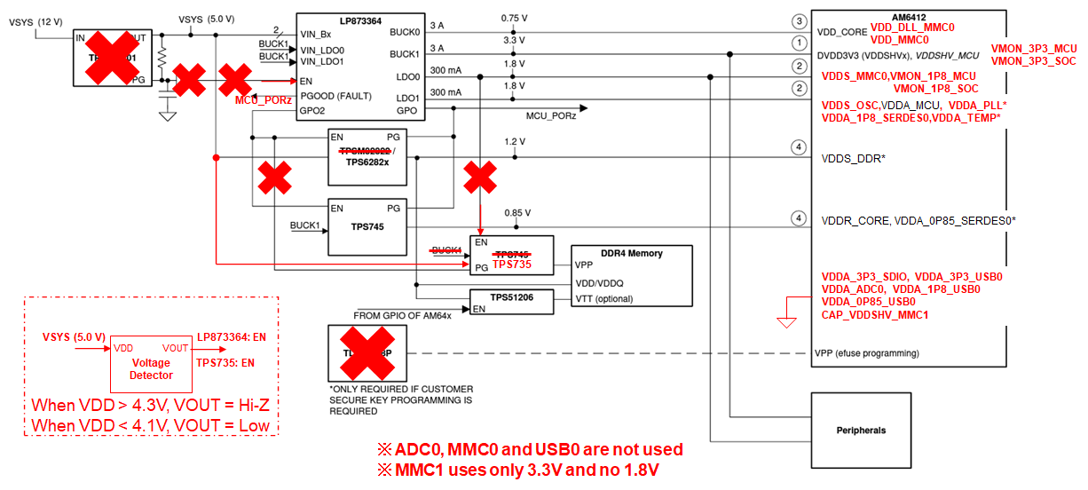
Can the EN pin be connected to VSYS (5V) along with the VANA and the VIN_Bx power pins? If not, how should the EN pin be connected?

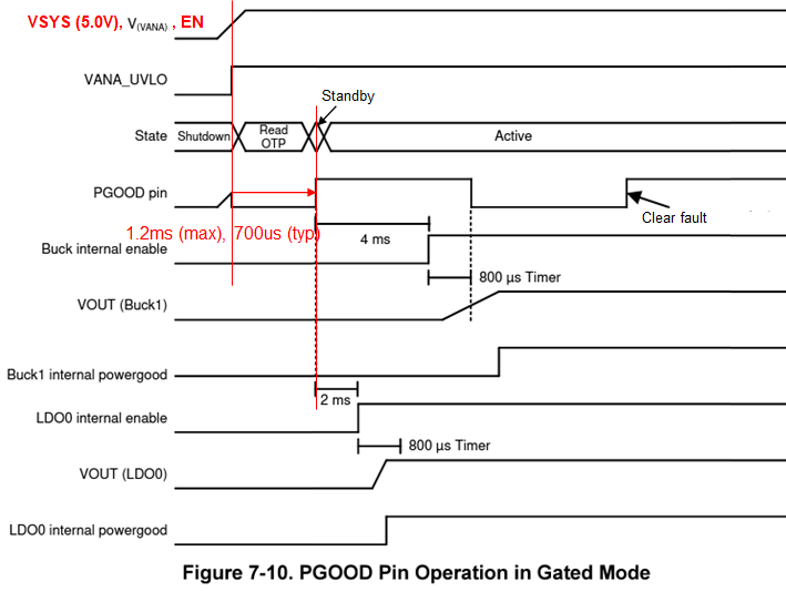
PGOOD is set to active or asserted state upon exiting the OTP configuration as an initial default state.

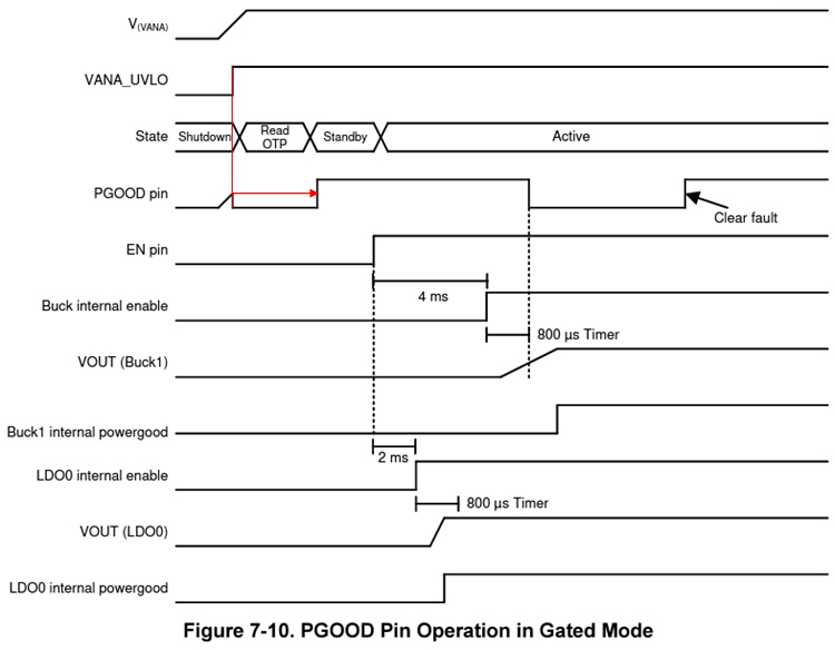
What is the delay between the V(VANA) voltage being above the VANAUVLO threshold level and the PGOOD pin being asserted?

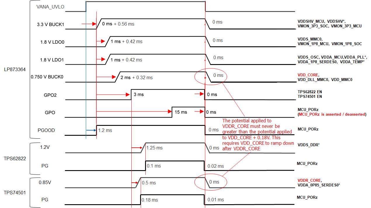
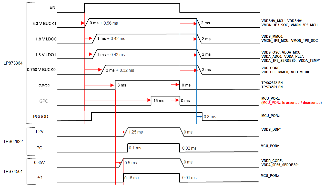
Our customer connects the PGOOD pin to the power-on reset pin (MCU_PORz) of the AM6442 along with the GPO pin and other power supply PG pins.

Does this connection work correctly to power-on reset the AM6442 both under normal and fault conditions? If not, how should the PGOOD pin be connected?

Best regards,

Daisuke

  • Hello Daisuke,

    EN pin can be connected to the 5V supply as well.

    PGOOD delay from VANA_UVLO rising edge is 1.2ms max, 700us typ.

    I don't see issues with this connection.

    Thanks.

    Regards,

    Tomi Koskela

  • Hi,

    Thank you for your reply.

    When the EN pin is connected to the 5V power supply along with the VANA power supply pin, when does the start-up sequence initiate for the regulator outputs using the EN pin?

    Does it have the same delay as the PGOOD delay from VANA_UVLO rising edge, i.e. 1.2ms max, 700us typ?

    Best regards,

    Daisuke

  • Hello Daisuke,

    Yes that is correct. There is additional 1.2ms(max) delay on startup.

    Thanks.

    Regards,

    Tomi Koskela

  • Hi,

    Thank you for your reply.

    I understand the following for the start-up sequence.

    Best regards,

    Daisuke

  • Hi,

    I have another concern about the EN pin being connected to the 5V power supply (VSYS).

    Since the shutdown sequence cannot be initiated using the EN pin, the shutdown is done by turning off the 5V power supply (VSYS).

    The AM64x power-down sequence requires that the potential (TPS745 which is turned on/off by GPO2) applied to VDDR_CORE must never be greater than the potential (BUCK0) applied to VDD_CORE + 0.18V during power-up or power-down.

    e2e.ti.com/.../3955919

    When shutdown is done by turning off the 5V power supply (VSYS), can the AM64x power down sequence requirement be met?

    Best regards,

    Daisuke

  • Hi Daisuke,

    Yes that is actually a very good point. Did not think about the shutdown case. That is why the pre-regulator PG is used for the EN pin control in the proposed power tree to make sure there is sufficient time for the shutdown sequence. If EN is tied to supply voltage directly, it means LP8733 will shut down with UVLO actually (all outputs disabled at the same time) and not with EN, and the shutdown sequence is not as intended.

    When deviating from the proposed power tree it is always good to check the operation on bench to make sure there are no surprises. 

    Thanks.

    Regards,

    Tomi Koskela 

  • Hi,

    Thank you for your reply.

    I understand the power-up/down sequence as follows.

    Our customer will make sure that the potential (TPS745) applied to VDDR_CORE must never be greater than the potential (BUCK0) applied to VDD_CORE + 0.18V during power-down.

    Best regards,

    Daisuke

  • Hi Daisuke,

    Also note that if the LP873364 shuts down with UVLO, the bucks won't ramp down with the preset slew rate. They will be just disabled and the resistive pull-down will discharge the outputs and it can take longer than with the intended ramp. And there is 3.3V BUCK1 and if the input voltage drops below 3.3V + 0.8V = 4.1V (0.8V is the specified minimum difference between input and output voltages) the 3.3V output voltage can go out of regulation and trigger PG fault.

    So initiating the shutdown with EN signal instead of waiting for UVLO is more controlled way for the shutdown case. 

    Thanks.

    Regards,

    Tomi Koskela

  • Hi,

    Thank you for your reply.

    Our customer uses a voltage detector for the 5.0V power supply to control the EN pins.

    The timing of the EN pin toggling depends on the slew rate of the 5.0V power supply, so they will make sure it works properly.

    Best regards,

    Daisuke

  • Hi Daisuke,

    Ok, sounds good!

    Thanks.

    Regards,

    Tomi Koskela

  • Hi,

    Thank you for your reply.

    I have one more question.

    Can the 3.3V BUCK1 output voltage go out of regulation at a voltage greater than 3.3V + 0.8V = 4.1V and trigger PG fault?

    Our customer wants to fix the thresholds of the voltage detector, but is concerned that the 3.3V output voltage can go out of regulation before the EN pin is driven low.

    Best regards,

    Daisuke

  • Hello Daisuke,

    As long as input voltage is >4.1V and load within specified limits there is no reason for the 3.3V buck to go out of regulation. 

    Thanks.

    Regards,

    Tomi Koskela

  • Hi,

    Thank you for your reply.

    Our customer will use 4.3V as the threshold for when the voltage detector outputs Low to initiate shutdown by the EN pin as soon as possible.

    Best regards,

    Daisuke