This thread has been locked.

If you have a related question, please click the "Ask a related question" button in the top right corner. The newly created question will be automatically linked to this question.

TPS548A29EVM: Inrush

Part Number: TPS548A29EVM
Other Parts Discussed in Thread: TPS548A29

Hey I did some inrush testing with the TPS548A29EVM and I got some weird waveforms.

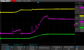
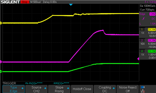
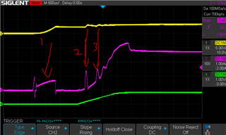
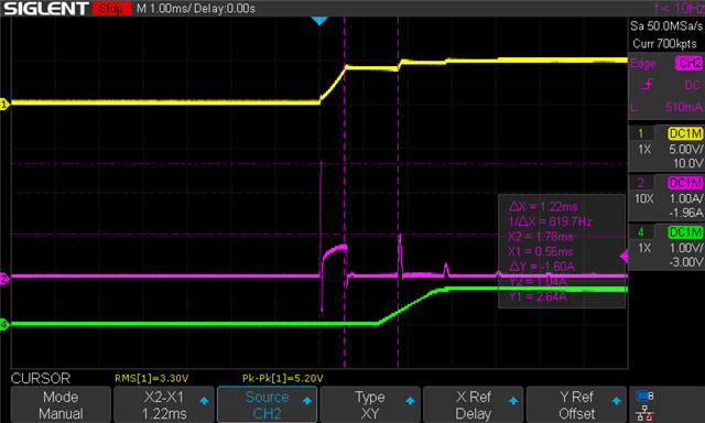
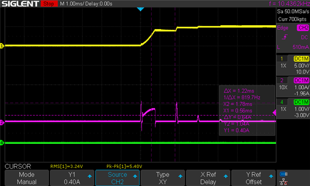
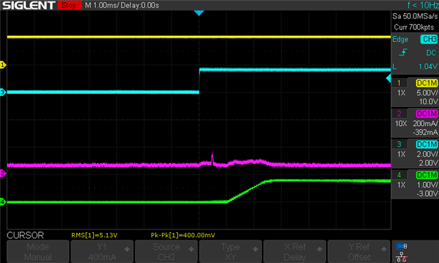
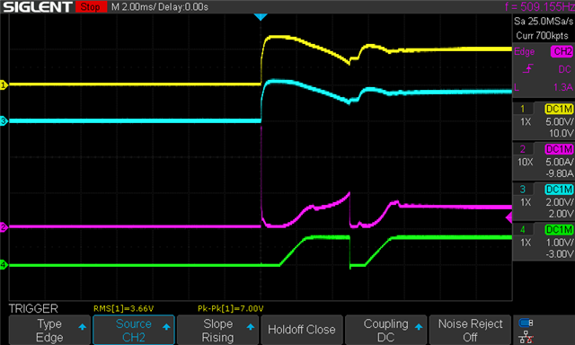
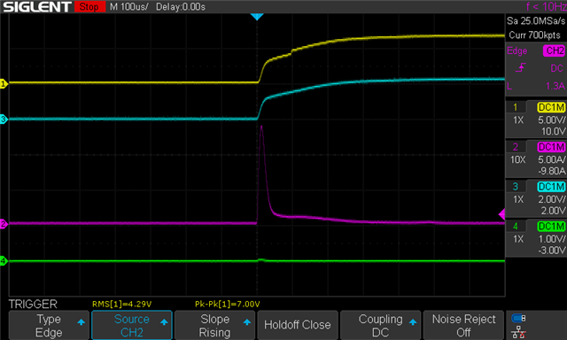
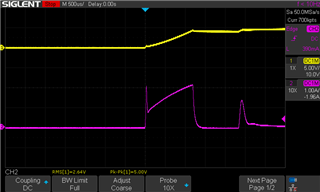
CH1 (Yellow): Vin, CH2 (Magenta): Iout, CH3 (Blue): Vout, CH4 (Green): SW

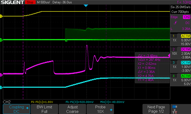
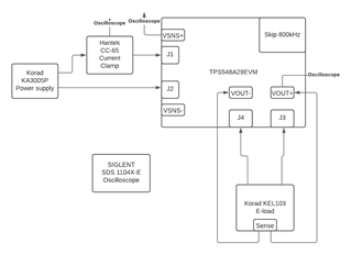
Eval is set to skip mode, 800kHz, output of 0.8V and a Vin of 5V. Loaded the output with 14A before turning on the powersupply at Vin.

Can you explain the reasoning for the multiple peaks? 

  • Hi Jerome,

    Our US team will check it and reply you soon.

  • What mode is the load operating  CC or CR mode.     

    I have tried to duplicate on the bench but my waveform looks different. 

    Can you capture the above waveforms with the ch1, ch4 DC coupled with IIN  and then capture with IOUT.  

    At no load, with DMM what is the input current with skip and fccm mode. 

  • 1) Hi the load is operating in CC mode.

    2) The above waveform's CH2 (Magenta) was actually IIN.

    Since then, I have desoldered C2 to get a closer representation of how we will use the design. Here are the new wave forms with a Eload set to CC at 14A and the eval using Skip 800kHz:

    CH1: VIN, CH2: IIN, CH4: VOUT

    CH1: VIN, CH2: IOUT, CH4: VOUT

    3) With Skip 800kHz, at no load, the input current is 0.1uA. With FCCM 800kHz, at no load the input current is 2uA.

  • thanks for capturing the waveforms.

    The output voltage and output current look correct on second image. 

    The input current # 1 does not make sense to me.   

    At #1 mark the input current is charging the input capacitors. okay.

    At #2 mark, the input current has a peak.   Some the input current is because of the output current,

    and maybe the switching frequency has increased and that will increase input current a little  

    but why is the input voltage increasing and the input current simultaneously. 

    When I see input current peak, i am would expect the dc/dc to sink the current if there was an issue with dc/dc device.

    If the power stage fets are on simultaneously, the input current can peak but I would expect the input voltage to droop. 

    Can you take the same measurements but without the load enabled. 

    Also, take the same measurement but with the TPS548A29 device disabled (J5 connector).  IIN, VIN, VOUT.

    Also, take a measurement with the input voltage at the steady state voltage and then enable the device capture IIN, VIN, VOUT.  

  • 1) No load

    CH1: VIN, CH2: IIN, CH4: VOUT

    2) J5 Disabled

    CH1: VIN, CH2: IIN, CH4: VOUT

    3) On Enable event

    CH1: VIN, CH2: IIN, CH3: ENABLE, CH4: VOUT

  • I tried redoing the test with a different power supply and I got these results:

    1) 14A Eload Inrush:

    CH1: VIN, CH2: IIN, CH3: ENABLE, CH4: VOUT

    2) No load

    CH1: VIN, CH2: IIN, CH3: ENABLE, CH4: VOUT

  • Your input supplies seem to have some interesting characteristics.   

    On the first supply, can use power up without the EVM connected and use a bulk cap and measure in the inrush current into the cap. 

    The first supply has pulses when the device is disabled.   I have no explanation other than the input supply is acting up.   Can you verify with the above experiment. 

    On the second supply, the inrush current is similar to my measurements.    However, the input voltage is drooping which causes the device to turn off once the input voltage goes drops less the ~3V to 4V.

    Can you sketch your test setup and if ok give the equipment model numbers. 

    I am wondering if the test setup can we tweaked  with supply #1 to get a better  measurement.

    the idea would be to add bulk cap near the lab supply.    If the lab supply pulses current the bulk caps will absorb the current and the DUT input voltage will transition more smoothly and the current pulses reduce

  • 1) 1st power supply (Korad KA3005P) set to 5V, inrush current into 470uF cap:

    CH1 (Yellow): Voltage across cap, CH2 (Magenta): Highside current into cap

    2) Setup drawing

    3) The model number of the second power supply is BK Precision 1150

  • Thanks for the data.   The korad power supply has some problems.  I am not sure how to help. 

    I googled the korad model and there were reviews on amazon stating the output terminals can have output voltage present when disabled.

    i did not see any reviews describing the phenomenon discussed above. 

    The BK has a 3A current limit,  use the BK supply with a lower eload setting and run the test.   

     I think the 3A output of the supply at a 5V iinput s not enough for the 14A at 0.8V

    Use a higher input voltage or lower the eload settings and see if the BK gives a better startup.