


Other Parts Discussed in Thread: BQ24103,
Hello,
Our team is currently debugging our BQ24104 charger IC board. We are comparing our results with the data we got from the BQ24103 EVB. Here are our observations
A. With the 2S4P battery connected, when we connected the 15V Power Adapter in the input.
1. There is little to no current draw. It is around 30mA from the power supply.
2. The battery voltage is slightly discharged to around 8V.
3. When we plug the battery and 15V power adapter to the BQ24103 EVB, we are seeing the expected current draw of 1.5A.
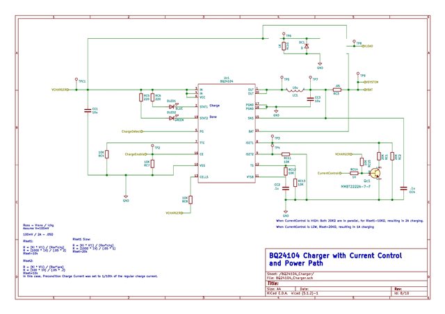
4. The STAT1 and STAT2 LEDs are OFF
5. We measured that the PG pin is pulled to ground via measuring the resistance between the pin and the ground. It was open load when the 15V adapter not connected and it was near 0 ohms when the 15V was connected to the input.
6. Charge Enable pin is tied to the GND. RC7 was changed from 10k to 0 ohms.
7. We are measuring the correct voltages in the VTSB and TS pin. It is similar to the VTSB and TS pin voltages on the EVB. (VTSB=3.2V and TS=2.216V)
8. We are measuring around 0V in the ISET1 and ISET2 Pins
B. With the 2S4P battery removed and the 15V Power Adapter connected
1. In the EVB board, we probed the the BAT pin of the charger and we observing a square wave that goes from 0V to around 8.4V. We know this is expected because of the battery detection process as noted in Section 8.3.16 of the BQ241xx datasheet.
2. In our Charger IC board, we are measuring a constant 14.46V in the BAT pin instead of the battery detection voltage.
We would like to know how should we go about debugging this issue. It was working up until recently. How would we know if the charger IC is damaged since we are still able to measure the expected voltages on some pins (TS, VTSB, PG).
The setup for testing our charger IC board before it failed is as follows
Input Voltage: 12V
Battery: 2S4P
Fast Charge Setting: 2A
Current Schematic:
Thanks,
Deniel
