Hello.
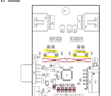
I have a question regarding the recommended placement of the components involved in the daisy chain communication between BQ79606A ICs. We have boards with multiple BQ (for example, 2 on each board). In addition to this, several PCBs are connected with cables. As recommended in the datasheet SLUSDQ4 and also in the design recommendations SLUA811C we use capacitor isolation between BQs on the same board and capacitor and choke for communication between boards.
Section 13 (Layout considerations) of SLUA811C recommends placing isolation capacitors near the edge of the board and chokes near the cable connector. Then it says "Place the series resistors and TVS diodes next to the BQ79606A-Q1." My question is how to interpret this sentence. So, my first question is: Does it means that series resistors and TVS should be as close to the BQ as possible?
Another issue is the keep out on internal copper layers and bottom layer (assuming components are placed in top layer, of course).
- Which components should be placed above keep out of internal layers? Should TVS and series resistors have keep out on all layers below them or this requirement is only for choke and isolation capacitors?
- Assuming TVS and resistors are close to the BQ and choke and capacitor are close to board edge: Should there be a keep out on all layers below the tracks that connects them? (In our pcb, this distance is 10 cm aprox.)
Thanks in advance for your reply.
Regards