This thread has been locked.

If you have a related question, please click the "Ask a related question" button in the top right corner. The newly created question will be automatically linked to this question.

LMZ13610: Increasing Stability

Part Number: LMZ13610

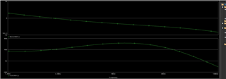
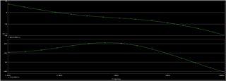
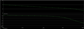
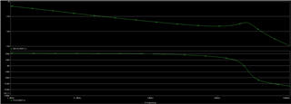
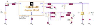
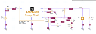
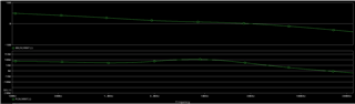
I am using the PSPICE average model to understand the stability of my design. i am running 28V in, 5V out, 1.25ohm resistor for a load of 4A. To be consistent with the datasheet graphs, I am using x2 330uF (tantalums), x1 47uF ceramic, and x1 0.01uF ceramic. Based on this, I get a phase margin of ~46deg at a crossover frequency of 3kHz. I am trying to find ways to increase the phase margin. Decreasing the capacitance will help as long as I can still meet my load transient and tolerance requirements. I have also found that increasing the ESR for the 330uF tant, will also help.

Are there any other ways or suggestions for increasing phase margin? Is it typical for the part to be somewhat low for minimum capacitance per the datasheet?

  • Hello David, What is the load step output voltage tolerance specification? Your output capacitance seems like a decent amount even for a 4A load step. The output cap is pushing your crossover to a low frequency perhaps for the given internal compensation.

    Maybe if your application requires that amount of output capacitance, you could introduce some additional phase boost with an ESR zero (which you have found to be successful), or a feed-forward capacitor.

    For the later, find below appnote for CFF calculation.

    cff-calculation.pdf

  • The problem becomes when I start looking at the DC tolerance over line, load, IFB, VFB, etc...Since VFB has a 20mV tolerance, that becomes a dominant factor that pushes the RSS value of the DC tolerance much higher. Right now with that a little more capacitance than stated above, I'm seeing ~50mV undershoot/overshoot with ~12mV rippled. Because what I mentioned above, I cannot afford more than another ~70mV of transient. This is all with a 10nF CFF cap as recommended by the datasheet.

    The transient response looks fine, but when I insert the CFF in the average model circuit, it looks like it it has a crossover frequency much much lower.

    Here is the BODE of when there is no CFF, with no adjustments to the 330uF tant ESR.

    Here is the BODE of when CFF is 10nF.

    Here is the BODE of when there is no CFF, but ESR is adjusted to be higher.

  • as a followup, I did look at the effect of changing the CFF cap value in the average model circuit. If the tant cap ESRs are not increased, small CFF values of 10's of pF do not have much of an affect. Once you start getting into the nF's (4.7nF), it pushes the crossover frequency to the left (see graph below).

    When the tant ESR are increased without the CFF in the model to get to a reasonable phase margin (crossover frequency still fairly low). When you add the CFF of 10pF in, you start seeing peeking but the entire gain margin shifts down while phase shifts up. It seems like it's doing the opposite of what the app note was specifying?

  • Hello David, a fellow team member will get back to you shortly.

  • Hi David,

    Let me look further into this and get back to you.

    Regards,

    Jimmy

  • Hi David,

    Perhaps the first question I have is how much PM are you looking for?

    From most apps perspective, a stable design is one where PM >40-45deg and Fcross is around 1/10th the switching frequency.

    Both cases here already satisfy the criteria, unless you are looking for something else.

    The value you have also follows the typical BOM of the LMZ13610EVM (https://www.ti.com/lit/ug/snva478c/snva478c.pdf) and should not have any issues with stability. 

    If anything, you can reduce your output capacitors to shift your crossover further out from 3kHz to take advantage of the phase bump and still satisfy being 1/10th the switching frequency.

    Regards,

    Jimmy

  • I was looking for around 60 for a little more margin. The question that I have is based on my simulation results of whether or not the bode plot results are consistent with how adding CFF into the circuit? The first graph shows it without CFF, and the second is with CFF=10nF. Based on the app note provided, it seems like the CFF is supposed to help increase the cross over frequency, but in this case, it looks like it decreased it <1kHz. Is that low of a frequency an issue? I assume it should only affect the time it takes for the control loop to stabilize a given load transient?

  • Hi David,

    My understanding also is that a CFF will shift the crossover higher for the phase boost since you are introducing an extra zero into the control loop. 

    As it stands I would suggest adjusting your output capacitance and ESR first before using CFF, there may be some inconsistency in that model.

    Can you send me the modified PSPICE average model that you are simulating with to see why this is happening?

    Regards,

    Jimmy

  • Let me take a look at this and get back to you after some simulations.

    I just came back from time-bank and thank you for your patience.

  • Hi David,

    Below is a before/after CFF simulation I did with the base PSPICE model modified for 28Vin|5Vout|4A|600uF.

    Before:

    After

    The results show that adding the Cff shifted the crossover to the right towards higher frequency.

    Please try using my PSPICE model as a starting point and adjust to your desired application.

    LMZ13610_PSPICE_AVG_TI.zip

    Regards,

    Jimmy

  • I see what the problem is, it is the connection of the CFF to the VOUT versus node between LINJ and CINJ. For smaller capacitors (ie: 10pF), you don't see a change when the CFF is connected to either VOUT or LINJ/CINJ. When you use a 10nF, it gives you different results. Hooking it up your way is consistent with how the CFF should work. Thanks for the information.