


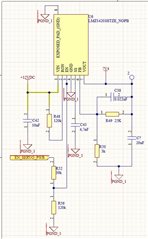
We have designed a PCB using 2 LMZ14203HTZE_NOPB, one for 5v (from 12V) and another for 7.4V (from 12V too). The first one is just fine, Vout is OK and the VFB is 0.8 as expected. The other one, instead of gives 7.4V it gives Vo=8.74V. I measured in its FB and it is 0.92V instead of 0.8V , if you analize the resistor divider according to this 0.92V instead 0.8V, this 8.74V in the output is obtained...
In the datasheet mentioned something about overvoltage protection, but i have modify the Cout to improve the output ripple (decreasing ESR) using better ceramic capacitors, also changing the capacitor on the VFB net... also i have modify the resistor dibider exacly the same values as the 5V and it gives 6V (becasue of its 0.92V VFB...). Nothing change.... aways 0.91V-0.93V on FB pin.
Is it normal that LMZ14203H pin FB exist 0.92V instead of 0.8???
I would appreciate any suggestion, because i am lost right... the only thing i have not do yet change the LMZ14203HTZE...
Thanks in advance and best regards.

