Hi. I´m doing some Tests with the LMR3650RREVM and I have some questions. In the Datasheet of LMR36506 I found out that "Which
mode the LMR36506 operates in, depends on which variant from this family is selected". That means, if my LMR36506 is lightly loaded, I should use the LMR36506RRPER (better efficiency when lightly loaded), otherwise the LMR36506RFRPER. In the Datasheet of LMR36506RREVM(Evaluating Module) I found out that the LMR36506RRPET was used. I looked at the Device Marking; it´s the same as the Device Marking of the LMR36506RRPER (MC04). That means that the 2 Converters are basicly the same. I´m now a little confused becaus the Datasheet of the Evaluation Module says as follows:
"JMODE/RT - Use this jumper to select the mode of operation in a MODE/SYNC trim part.
Connecting a jumper between pin 1 and 2 cause the IC to operate in PFM (Pulse Frequency
Modulation) mode for a higher efficiency at light load. A jumper between pin 2 and pin 3 causes the IC
to operate in FPWM mode (Forced Pulse Width Modulation) mode. By default, the jumper is connected
between pin 1 and 2. ---> Actually between 2 and 3 (found in the Schematic "Place SH-J1 on J2 (JMODE/RT) in pin 2 and 3")
In an RT trim part, connecting this jumper from pin 1 and 2 sets the switching frequency to 2.2 MHz
and connecting this jumper from pin 2 and 3 sets the switching frequency to 1 MHz."
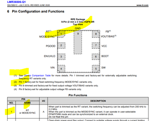
While the Datasheet of the LM36506 says that connectin RT to GND will set fhe SwitchingFrequency at 2.2MHz, and connecting the RT to VCC will set the Frequency at 1MHz. By placing an RT Resistor to GND will set the Frequency from 200 kHz to 2.2 MHz (depending on the value of the resistor).
Am I missunderstanding or am I missing something? The 2 Datasheets say different things. The one says that the Mode depends on the selected family, and the other says that you can change the Mode by connecting the RT Pin to VCC or GND.
Thank you very much in advance, and sorry if I missunderstood something.
Andrei