This thread has been locked.

If you have a related question, please click the "Ask a related question" button in the top right corner. The newly created question will be automatically linked to this question.

TPS54160A: Maximum Input Ripple Allowed Without Impacting Output Ripple

Part Number: TPS54160A
Other Parts Discussed in Thread: TPS54160

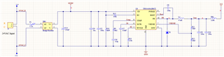
I have an application (HVAC) where the power source is a 24VAC transformer. We have limited space and ran some preliminary tests to check what the input voltage would look like, please see attached document. We are going to regulate down to 3.3V and the maximum load will probably be ~500-600mA when connecting to WiFi and maybe ~100mA in other conditions. The current switcher design we have is this:

From the data we collected (using an electronic load) even at 470uF there is over 6Vpk-pk. We're hoping to use as little a size as possible for the electrolytic cap after the bridge so we can reduce the overall footprint.

AC Bridge Rectified Measurements.pdf

Is there any reference data on this or any helpful advice on what we "can get away with" in this design?

Thanks,

George

  • Hi George

    For U8 to operate normally and function smoothly, it is important that the input voltage for U8 never be lower than the Vinmin(3.5V) or dropout voltage(3.3V).

    The heavier the load is, the larger the ripple there will be. As you mentioned the maximum output current of U8 will be around 500/600mA, I wonder why use 410mA as the maximum input current for U8 in the attached AC_Bridge Rectified Measurements? If the load is lighter , the capacitor can be smaller to gain the same voltage ripple.

    Also, the larger the capacitor is, the bigger the inrush current of DB1 will be.

    Best regards.

  • Well the input voltage certainly won't drop anywhere close to 3.5V so that's not an issue. You're right about the load current. I was thinking output current when the measurements were taken so this is far beyond what the TPS54160A will be.

    But this still leaves me to question how much ripple can be on the input for the TPS54160A to have a stable output? I don't have the prototype design done yet as I'm concerned how much room to leave for the bulk cap after the diode bridge. I'll have to go back and take some additional measurements but looking at the extreme case of 30Ω load with the 100uF cap I see the input waveform to be about 10V minimum to 36V maximum so a peak-to-peak of 26V. Is something this drastic as an input to the TPS54160A still going to give a stable 3.3V output?

  • Hi George

    Do you mean by adding measurement, the output current of DB1 will be larger than normal operation?

    It is ok to gain stable 3.3V output under 10V-36V Vin since the TPS54160 can fastly adjust the output voltage through inner feedback loop. While the Vout may contain some ripple which has the same frequency as Vin which is 100Hz.

    Best regards.

  • Hi Gui,

    Sorry for the confusion. No I meant that when I took the initial measurements I applied a load on the DB1 but I was thinking of what the output current of the 3.3V rail would be, not what the current would be on the input to the TPS54160. So I took measurements with a much higher load on DB1 than what would actually be seen in the application.

    So you are saying that I mostly just need to confirm that the input voltage does not drop below maybe 4-5V and since the input will be at 120Hz it is slow enough that the TPS54160 will handle the input voltage swing without a problem. I might have some increased ripple on the output rail but everything should operate normally?

  • Yes that's it.