This thread has been locked.

If you have a related question, please click the "Ask a related question" button in the top right corner. The newly created question will be automatically linked to this question.

TPS2597: LTSpice simulation ending with time step too small

Part Number: TPS2597

Hi,

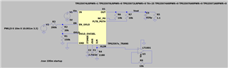
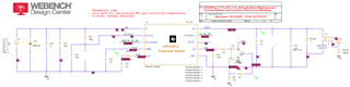
I am simulating TPS25974 with a SPICE model I created based on the model TI publish. 

I had to add a model for 'DBREAK' diode as suggested by TI.

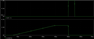
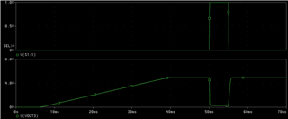
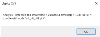
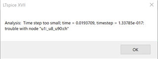
I simulate for 100mS but it gets stopped with 'Time step too small' error.

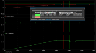
I then added an Op-amp buffer to the ILIM pin to monitor output current and  I get.

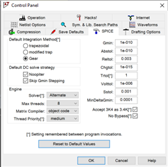
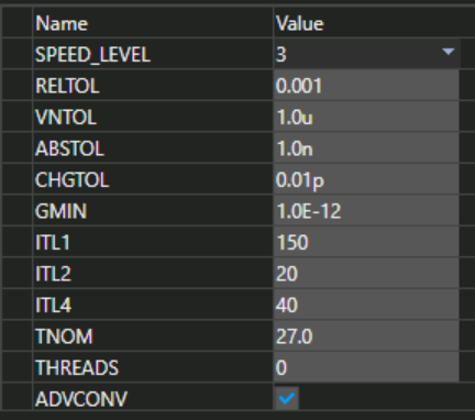
I tweaked the solver in LTspice but no luck.

Can you please help?

Cheers,

Kaushalya

  • Hi Kaushalya,

    This model is optimized for PSpice . Sometimes when step size or simulation time or schematic becomes too complex model can fail to converge. In PSpice we can use auto converge setting to make it work. I will recommend using PSpice for TI . Can you share your schematic and simulation setup details?

    Regards

    Kunal Goel

  • Hi Kunal,

    Thanks for your prompt reply. I am used to LTSpice and the speed of simulations and limited resources it needs on your PC. I will try to do it in Pspice for TI.

    Simulation setup: 100mS, all voltage sources starting from 0V

     3757.SIMs.zip

    Cheers,

    Kaushalya

  • Hi Kaushalya,

    Please try using these settings. Also if we can choose maximum  step size in LTspice , make it 100ns.

    Also one more recommendation can you try testing first with some low cap maybe 220uF and no resistive load. 

    Regards

    Kunal Goel

  • Hi Kunal,

    I did my simulation using Pspice and managed to get the output I was aiming for apart from transient overload condition. Following is my circuit.

    I use TPS25974LRPWR.

    I have changed the circuit slightly to suit our needs. An op-amp non-inverting amp with gain of 4 is used to derive the current monitor signal from ILIM output.

    For short circuit simulation, I have added a voltage controlled sw, S1 and turned the S1 on @ 50mS and off at 63mS. My transient blanking Itimer cap is 15nF, which should provide me 10mS of blanking period before the trip fires.

    Problem 1. The Itimer voltage output doesnt seem to change when short circuit occurs. It is kept constant @ 2.56V. According to Itimer should start to drop when the overcurrent condition is detected.

    Problem 2. When created a short circuit of < 10mS, it shouldnt trip (As I understand) as my load transient blanking is 10mS. But as shown below, the Vout trips.

    With op-amp non-inverting connected to GND, 

    How can this behaviour explained? Is there a better way of interfacing to ILIM to derive the current monitor signal?

    TPS2597x_PSPICE_TRANS.zip

    Cheers,

    Kaushalya 

  • Hi Kaushalya,

    When short happens then ITIMER functionality is not there. For current greater than 2*ILIM device will turn off very fast overriding ITIMER . When current is between ILIM and 2*ILIM then only ITIMER happens.

    This way of monitoring current through op-amp looks fine. ADC can also be used if you wanna feed signal into some controller.

    Regards

    Kunal Goel

  • Hi Kunal, 

    Thanks for your reply. Very good point. So I have introduced some series resistance to short circuit path. Now the short circuit current would be 5.9A which is < 2x4.5A. 

    But as you can see from the image below, the ITIMER remains constant during this. However the output behaviour seems correct.

    What is your opinion?

    Cheers,

    Kaushalya

  • Hi Kaushalya,

    Please share file with me. I will also try running it.

    Regards

    Kunal Goel