This thread has been locked.

If you have a related question, please click the "Ask a related question" button in the top right corner. The newly created question will be automatically linked to this question.

TPS65261-1: Excessive voltage ripple on 3v3 output

Part Number: TPS65261-1
Other Parts Discussed in Thread: AMC3301, TPS65261, TPS65263

Hello,

I'm a relative newbie to using these devices and wanted to configure it originally for 1.5V, 3V3 and 5V, some way into the design, we ditched the 1.5V so are only using outputs 1 and 2.  for 5V and 3V3 respectively. I bought and configured a TPS65261-1 EVM pretty much along the lines suggested by your own documents and it all seemed to work ok. Now I seem to be encountering some significant voltage ripple in the actual application and am wondering if you could take a look and maybe offer some suggestions as to why this might be?

The circuit we have is as below:

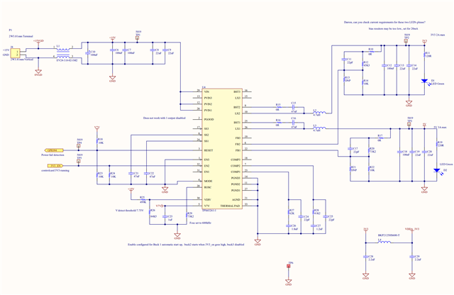
The 3V3 loading is not that high at the moment, maybe 0.5A or so. 

The 5V feeds an  RDC sensor (AD2S1210 )and a TMS control card with an F28379D to generate the onboard 3V3 and 1.5V which is used for the TI microprocessor.

The 3V3 load consists of various peripheral sensors, and interface devices  with onboard converters e.g AMC3301's, ISO7840F isolation buffers etc, CAN interfaces, SPI buffers current sensors voltage sensors etc. 

We do have a common ground between the TMS 3V3 circuit and this  external 3V3 circuit.

Some indication of the issue:

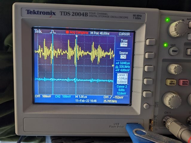
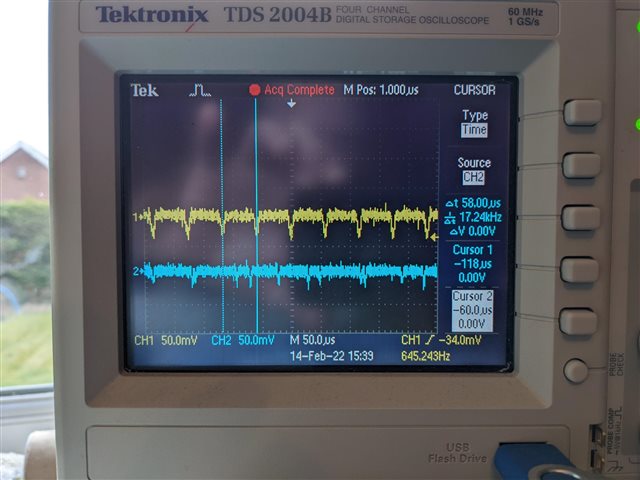
Looking at the ripple only, we can see the 3V3 has ~300mv ripple which seems to have a repeating envelope at around 330kHz or so with the higher frequency at around 7MHz  There is no obvious other cause for this e.g PWM operating, external power coupling etc,  the micro is just sitting there not running any program.

Looking at the 5V output (which feeds the control board) this seems to be nice and stable.

We see a similar situation with the 15V input to the converter, this is from a separate isolating DC/DC converter but doesn't seem to be suffering excessive ripple.

Unfortunately, this ripple is upsetting the various sensors and polluting the analogue sensing circuits.

We have placed a couple of CLC filters to isolate some sensitive external sensors and devices as much as possible:

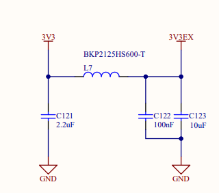
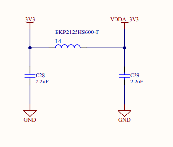
And I did wonder if these might be causing some ringing or instability, but at this stage I'm just not sure where to start. Any pointers you might be able to proffer would be welcome?

regards

Steve


  • Hi Steve,

    Thanks for coming to us with your queries. I will give you reply soon after this weekend.

    BRs

    Lucia

  • Hi Lucia,

    Thanks for you response.

    I think all is ok after all. I had another look at my setup and it seems common mode ground noise in the scope was the probably the issue here. Moving my scope grounds around has eliminated the bulk of what I was seeing before.  I am getting some issues with pickup on the analogue inputs (which is what brought me to look at the 3v3 and assume that was the source) but I think that is probably more to do with my own circuit than the TPS device now.  I'll continue looking about to see if I can make some improvements in that area. 

    regards

    steve

  • Hi Lucia,

    Ok so after closer inspection I still have a bit of a question, Looking at the scope below which is looking at the AC ripple on the 3V3 output (yellow) and the 5V output (blue). There seems to be a monotony in the output at 17kHz, which is a bit unexpected. In fact I can actually hear it working, which is also unexpected as this device should be switching at 600kHz. Any thoughts? Is this expected behaviour if the load is low? 

    regards

    steve

  • Hi steve!

    Lucia will reply you soon!

    Shuai

  • Hi Steve,

    Thanks for coming to us with your queries. Sorry for late reply since I have several cases in hand.

    1. For the first question about 3.3V noise, I agree with you that it seems to be caused by probe. Could I ask what is your test point when it shows noise and when the noise is improved? What does "moving scope grounds around" mean?

    2. For the second issue regarding low frequency AC ripple, I have several questions and suggestions shown below:

    (1) Could you please clarify the actual output current of Buck1 and Buck2 when the waveform is captured? Could you also capture the waveform of LX1 and LX2 and check whether if there is any abnormal? Have you tested the bode plot and could you please send me the bode plot?

    (2) The loop compensationTPS65261 and TPS65263 are similar. 

    You can kindly use TPS65263 Webench to check its stability. I think its a good simulation tool for you to check this problem.

    https://www.ti.com/product/TPS65263?keyMatch=TPS65263&tisearch=search-everything&usecase=GPN 

    (3) What is the value of Buck1 and Buck 2 total derated output cap? It is suggested to add 1-2* 22uF output capacitor or decrease R27 and R28 to 10-20k to check whether 17kHz ripple still exists.

    Let me know if there is any more concern.Thanks!

    BRs

    Lucia