This thread has been locked.

If you have a related question, please click the "Ask a related question" button in the top right corner. The newly created question will be automatically linked to this question.

TPS2493: High Powered - Brushed DC Motor Application

Part Number: TPS2493
Other Parts Discussed in Thread: TPS2492, TVS3300

Hello TI people,

We are designing a soft starter controller for our vacuum motor using the TPS2493 chip.

We have attached the design calculator for this motor which is running at a maximum 24V, 25A.

The motor load has an inductance of 0.763mH and 0.8ohm.

We have been facing issues with shorted MOSFETs and disabling the auto-retry function on the TPS2493 chip.

We have the following questions:

How to disable auto-retry on the TPS2493 chip?

Apart from shorting OV to ground, our circuit follows the design example schematic. (Attached Schematics)

Is shorting CT pin to ground sufficient?

Once the hotswap controller is fully turned on (i.e. PG goes low), can we ramp the motor straight to 100% PWM using motor driver? (There might be inrush current because of the Brushed DC motor nature)
IPP016N08NF2S - MOSFET.xlsx

TPS2493 Schematics Design.pdf

  • Hi Calvin,

    Welcome to e2e!

    Thanks for reaching out to us. Avishek will get back to you on this query soon. 

  • Thank you! Please help us on this one :)

  • Hi Calvin,

    I will get back to you today soon. 

  • Hi Calvin,

    Please see the responses to your queries below.

    How to disable auto-retry on the TPS2493 chip? Avishek: It's recommended to use TPS2492.

    Is shorting CT pin to ground sufficient? Avishek: It's not recommended to do so.

    Once the hotswap controller is fully turned on (i.e. PG goes low), can we ramp the motor straight to 100% PWM using motor driver? (There might be inrush current because of the Brushed DC motor nature) Avishek: After the Hot Swap MOSFETs are fully turned on, these can carry the complete load current and will allow to flow as long as it's less than the current limit threshold. 

    May I know the reason of using 61.9 kΩ resistance as gate resistors? Generally 10 Ω is recommended. 

    Please make RG as 10 to 100 Ω and CG as 10 nF. 

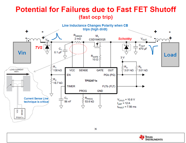
    One (1) SMAJ28A or TVS3300 or equivalent TVS diode needs to be used at the input. D1 should be TVS diode not Schottky diode. 

    Please see the modified design calculator. 

    IPP016N08NF2S - MOSFET - Calvin.xlsx


  • Thank you for your answer.

    I am currently putting 10 ohm for the gate resistor. The schematic that I uploaded is the old one.

    May I know why the TVS is required on the input side? TVS will prevent voltage overshoot from the input side, right? Is it because of the power supply on the input side or is it because of our inductive load on the output side? Do we need to use OV pin too? will the OV from input side damage the chip?
    And how do you choose TVS? our voltage is around 24V maybe +-5%, you selected 40V, is there any reason?

    How do we know if the MOSFETs are fully turned on? Can we detect it from one of the IC Controller pin? I just want to make sure that I will only give 100% power to the load only when the MOSFETs are fully opened.

    Does this system take care of the inrush current after MOSFETs are fully opened (during runtime), in my case the inductive load may draw inrush current if running 100% PWM direct from 0% PWM condition.

    May I know if the RG 100 Ohm and CG 10nF is true for all system (all current and voltage specs)? Because in the calculator there is no indication on how to choose the components.

    For TPS2493, is the fault time cutoff and auto-retry duration only controlled by CT? Can we make the fault time cutoff as short as possible but auto retry longer than 16x?

  • Hi Calvin,

    I will get back to you on Monday. 

  • Hi Calvin,

    Please see the responses below.

    May I know why the TVS is required on the input side? TVS will prevent voltage overshoot from the input side, right? Is it because of the power supply on the input side or is it because of our inductive load on the output side? Do we need to use OV pin too? will the OV from input side damage the chip?
    And how do you choose TVS? our voltage is around 24V maybe +-5%, you selected 40V, is there any reason? Avishek: TVS diode is used to clamp the input overvoltage during hot plug and fast turn off events. If you need the overvoltage protection feature in your system, you can use the OV pin. In the overvoltage at the input pin exceeds its absolute maximum rating of 100 V, the device may get damaged. 

    Please see this blog and app note regarding TVS selection. 

    https://e2e.ti.com/blogs_/b/powerhouse/posts/selecting-tvs-diodes-in-hot-swap-and-oring-applications

    /cfs-file/__key/communityserver-discussions-components-files/196/TVS-Clamping-in-Hot_2D00_Swap-Circuits.pdf

    How do we know if the MOSFETs are fully turned on? Can we detect it from one of the IC Controller pin? I just want to make sure that I will only give 100% power to the load only when the MOSFETs are fully opened. Avishek: PG\ can be used to detect whether the MOSFET is complete on or not. 

    Does this system take care of the inrush current after MOSFETs are fully opened (during runtime), in my case the inductive load may draw inrush current if running 100% PWM direct from 0% PWM condition. Avishek: No, the Hot Swap controller will have current limit feature only. 

    May I know if the RG 100 Ohm and CG 10nF is true for all system (all current and voltage specs)? Because in the calculator there is no indication on how to choose the components. Avishek: CG calculation is indicated in the design calculator. 

    For TPS2493, is the fault time cutoff and auto-retry duration only controlled by CT? Can we make the fault time cutoff as short as possible but auto retry longer than 16x? Avishek: The fault time cutoff and auto-retry duration are only controlled by CT. We can't make the fault time cutoff as short as possible but auto retry longer than 16x.

  • Thank you Avishek, I will do the assembly and check if it is working!

  • Hello Avishek,

    I have got TPS2492 on my hand and tested with this parameter (passive components) on the list
    CSD18534KCS_TPS2492 - 24V.xlsx

    However when I try to test the overcurrent, the chip does not turn off the system, instead, it burns off my MOSFET.

    I think it makes my MOSFET to resistance mode but it still draws 8A so the heat dissipation of the MOSFET becomes very high and burn the MOSFET (this is just my theory on why the MOSFET burnt)

    May I know what happens to my design?


    Thank you!

  • Hello I just realized that you change certain things here

    • PLim from 700W to 150W
    • HotPlug from No to Yes
    • Number of MOSFET
    • Target Fault Time

    May I know what is the reason for all these changes? so we can input the number correctly for another system.

    for the MOSFET RQJA (junction temp), I purposely change to 16 deg because I am using heatsink for that

    For Multiple MOSFET, is there any consideration that I need to look for? Does the calculator already take care of the changes in other passive components?

  • Hi Calvin,

    I will get back to you by Monday. 

  • Hello Avishek, 

    I have tested further to check all the parameters on testing primarily on Vgs MOSFET, PG pin and FLT pin,

    I realized that there is a moment when the current (measured by clamp meter) almost reached 5A the current limit, the PG will just go high and low uncontrollable, with the Vgs MOSFET around 3.5V. This will result in heating up the MOSFET quickly which if you let it run, it will be burnt eventually.
    I am surprised that the chip did not turn off immediately and the FLT pin is still at HIGH logic, which means it does not even detect it as fault.

    After the test, I change the Ct (Timer Capacitor) to be 100pF, small enough so there is no time delay.

    Turned out that sometimes it will work according to what I want, it will turn off entirely, the Vgs goes all the way to 0.5V (not 3V) and FLT pin goes low. But it only work sometimes, 50% chance work as per normal, 50% works like the previous one (3V Vgs and PG uncontrollable)

    Please let me know what is exactly happen here, thank you for your help!

  • Please share your latest schematic and the design calculator on which you are working now and facing the issue. 

  • Hello Avishek,

    Please take a look at both calculator and Schematics

    TPS2492 24V 5A.xlsx

    TPS2492 24V 5A.pdf

  • Let's have a call. I am sending you friend request. Please accept that.