This thread has been locked.

If you have a related question, please click the "Ask a related question" button in the top right corner. The newly created question will be automatically linked to this question.

CSD18511KCS: why tr is commonly longer than tf?

Part Number: CSD18511KCS

Hi experts,

Hope you are doing well, and happy international women's day, if you're a female expert.

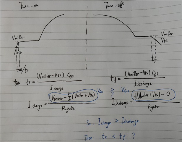
Why always the tr is  longer than tf?

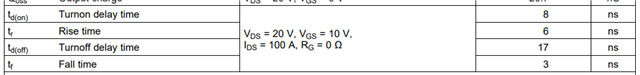
In my perspective, when turn-on or turn-off, the time needed is current(charging or discharging) related. Suppose there is the same Rgate, then the current will be decided by VΔ. Considering Vdriver= 10V, Vth=1.8V,  then we can get VΔ1>VΔ2. therefore, tr should less than tf?

Please help to review my calculations, in which 0.5(Vmiller-Vth) is used to simplify the average voltage during switching on& off.

Thanks.

 Marsh Cai.

  • Hello Marsh,

    Happy International Women's Day to you as well and thanks for the inquiry. I believe your analysis is correct. Rise and fall times are dependent on the gate drive current and Icharge is typically higher than Idischarge since there is more voltage available to generate the current. However, this may change if gate drive voltage is 5V or even 3.3V. Keep in mind, RG is made up of the gate driver resistance + external gate resistance + internal FET gate resistance. Gate drivers typically have lower discharge resistance. I am including a couple of links below. The first is a blog on how TI tests and specs switching times in our FET datasheets and the second is an application note on estimating power loss in a synchronous buck converter including common source inductance.

    http://e2e.ti.com/blogs_/b/powerhouse/archive/2015/07/16/understanding-mosfet-data-sheets-part-5-switching-parameters

    https://www.ti.com/lit/slpa009

    Best Regards,

    John Wallace

    TI FET Applications

  • Hi John,

    Thanks a lot for your valuable information. 

    Are you familiar with the LLC converter? If yes, could you kindly help me clear my confusion about the following-on question? Why primary MOSFET are always designed to work in ZVS condition to eliminate the turn-on loss. why not choose ZCS to eliminate turn-off loss? According to the blog you shared. The total time need for turn on (tdon+tr) is longer than that for turn-off (tdoff+tf). In my opinion, Soft switch technology should be used to maximize its value to eliminate the higher loss( turn-on loss).

    Thanks and BRs,

    Marsh Cai

  • Hi Marsh,

    I'm no expert on LLC converters. I'm going to redirect this to the HVP-HVC apps team.

    Thanks,

    John

  • Hi Marsh,

    In the LLC converter ZVS is preferred to eliminate the Coss losses during turn on. Also at turn off due to the output capacitor of MOSFET (Coss), turn off losses would be minimal. 

    However, in case of ZCS turn off, there will be a diode reverse recovery current which might damage the FETs. So, ZCS is not recommended.

    Please send me a direct message through e2e. I can share the app notes regarding this. 

    Thank you.

    Regards

    Manikanta P