Hi Team,
Our customer noticed a missing diagram in Figure 15 in the datasheet of LM2611. According to our customer,
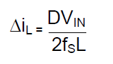
I am trying to determine the component values required for my application, using the LM2611 datasheet, however there are issues with the figures and equations stated. Section 7.3.2 begins to introduce the hardware however figure 15, which should be a waveform diagram showing inductor current values, is instead showing a circuit schematic (identical to figure 21). Additionally, equation 3 on the following page references a parameter "Ts" which is not defined anywhere in the datasheet.
Whilst the missing diagram in figure 15 is not that critical, I cannot determine the component values without a value for "Ts". Could you please confirm what "Ts" represents?
Regards,
Danilo