This thread has been locked.

If you have a related question, please click the "Ask a related question" button in the top right corner. The newly created question will be automatically linked to this question.

TPS62933: Question on TPS62933 design

Part Number: TPS62933

Hi

I will be appreciated if you can answer my  questions regarding TPS62933,

input= 10 - 26V

Vout= 5.4V  Iout =  3A  Fsw = 500kHz  Vout_ripple = <1%

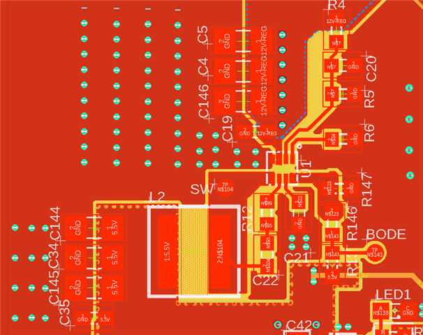
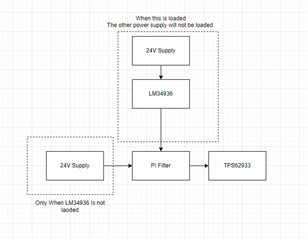
 Below is my layout and schematic,

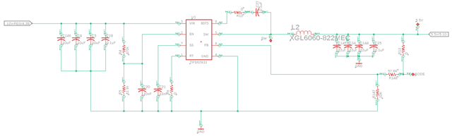
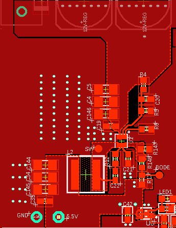
1. Can you take look at my schematic and layout and let me know if something need be changed

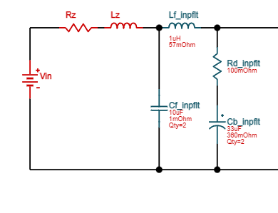
2. I am trying to add EMI filter to this

       a. Base Webench I need use 1uH 2.7A is that appropriate since I pulling 3A max. Also how do you calculate line impedance (is it impedance of pad)  

3. Do you have Gerber file of EVM board. 

4. Do you have excel calculator. 

5. What is different between this part and XTPS62933DRLR , since this part have less limit to purchase

Please let me know if you have any question.

Thanks

  • Hi  Amir

    Please see my comments below:

    1.The schematic looks good. Just one tiny thing here, I cannot read the voltage tolerance of the input and output capacitors, please make sure that you use appropriate caps.

    For the layout, it is a little bit strange for me that the pins of the device seem share the same copper. Would you please check that? Others look good.

    2.Do you want to add the common mode inductor?

    3. I will check this.

    4. Sorry that we do not have a calculator.

    5. The XTPS62933 is not the final version and it may have small bug, but we have done basic validation on the chip and it can be sold. But customers should know that there may be risk here. Since the supply is limited, customers sometimes in a hurry to use the devices, they would like to take the risk and buy the non-final version.

    Hope this helps.

    BR

    Ruby

  • Hi

    Thanks for the quick replay, below is the answer to your comments.

    1. All caps are rated for 50V

    2. I think picture was not taken correctly

    3. Yes, maybe common mode choke with capacitor, or maybe pi filter. My questions in Webenchhave different circuit with 2.7A inductor (

    DFE201612E-1R0M=P2) Do you how they are calculating this.

    Please let me know if you need any other information. 

    Thanks 

  • Hi Amir

    The layout looks good. Please refer to the Gerber file in the attachment.

    Gerber_NCdrills_IPC.zip

    For the EMI filter, which model do you use and would you please share the link of that? I am afraid this comes from the different team.

    BR

    Ruby

  • Hi Ruby,

    Thanks for providing the gerber file.

    I got the circuit from below link, I will be appreciated if you can let me know who should I ask this question from. 

    Power Designer (ti.com)

    Below is  low diagram 

    As you can see on above flow diagram this board can be powered through  LM34396 or through TPS62933.

    Please let me know if you have any questions.

    Thanks

  • Hi Amir

    I didn't notice this before, thanks for pointing out. I will check this and feedback to you.

    BR

    Ruby