Because of the Thanksgiving holiday in the U.S., TI E2E™ design support forum responses may be delayed from November 25 through December 2. Thank you for your patience.

This thread has been locked.

If you have a related question, please click the "Ask a related question" button in the top right corner. The newly created question will be automatically linked to this question.

UC1823: UC1823 output driver

Part Number: UC1823

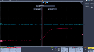
My question deals with the output stage of the UC1823.  I am using the UC1823 output to drive drivers that are 5V input rated.  So I am running the 5V VREF voltage into the VC pin and getting good results in the lab with it driving all the way to 5V with a good fast rise time between 0.84V and 3.4 V of only 6.8nsec.  So I don't understand the 2V typical saturation voltage.  That seems really high for a BJT totem pole stage.  What does this driver look like.  Can I reliably drive a 5V gate driver as I have been?  

  • Kevin,

    The UC1823 output drive stage is pure bipolar and fairly hefty at 1.5 A peak rating. The saturation values you are seeing in the data sheet are over temp and process and specified at IOUT=20 mA and IOUT=200 mA. If you are seeing much better results in measurement than what is published in the data sheet that's great but you may want to verify what your average gate drive current is estimated to be - is it closer to 20mA or more like 200mA? If your drivers are typical TTL threshold inputs and your average current is closer to 200mA, you could be in trouble. Around I=20mA looks to be good for TTL on the low end (turn-off) but what about the high end (turn-on). At I=20mA, we spec a worst case high level saturation of 2.9V but this is when 15V is applied to VC. At VC=5V we don't have test data. While your rise/fall times may measure good what about min/max PWM amplitude? You are looking at a legacy PWM that was never intended to drive GaN or 5-V MOS.

    Regards,

    Steve M