This thread has been locked.

If you have a related question, please click the "Ask a related question" button in the top right corner. The newly created question will be automatically linked to this question.

UCC28740: Increase the switching frequency

Part Number: UCC28740
Other Parts Discussed in Thread: TIDA-00701, UCC28180, UCC256403, PMP40766

Hello TI,

Currently I'm using UCC28740 IC with my Flyback transformer. I want to drive this circuit to 60V, 6A (Vout) output. 

https://www.ti.com/tool/TIDA-00701

Below is the Schematic circuit which I am following-


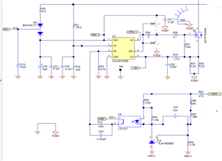
I want to drive above circuit to100KHz switching frequency. but after changing all the components still I have received only 31.25KHz frequency at 60V 6A resistive load connectivity. Below are the picture:

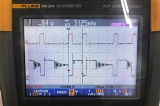
Freq= 31.25KHz Ton= 9.6uS Toff= 22.4uF T= 32uS Duty Cycle= 30%

Please suggest, How can I drive this to 100 KHz switching frequency and which component I need to change.

Thanks.

  • Hello Ravi,

    Thanks for posting this question about the UCC28740, specifying which reference design you're following,  sharing your the problem you're having, and how you've tried to fix it. 

    Before I answer your question about switching frequency, I'd like to address the following:

    Currently I'm using UCC28740 IC with my Flyback transformer. I want to drive this circuit to 60V, 6A (Vout) output. 

    https://www.ti.com/tool/TIDA-00701

    Here are my assumptions :

    1. 60V*6A=360W is the nominal power requirement, and that you may have maximum power requirement exceeding 360W (TIDA-00701 is for 100W, 24V out)
    2. The waveform image is showing the DRV signal on channel A and VDS of primary FET (Q2) on channel C.
    3. You're designing for universal AC input just like the TIDA-00701.
    4. You're using the same Wurth flyback transformer from TIDA-00701, 750343004 

    Here are my suggestions:

    While you could use the flyback topology for the isolated DC/DC block of this power supply, it will be more efficient to use an LLC topology at this power level. Try using PMP40766 as the starting point for your design, specifically schematic sheet 2 of 3. This design more closely matches your spec, and uses the UCC28180 and UCC256403.

    To address your switching frequency question directly, we need to understand why this is true for this case. I recommend you check out UCC28740 datasheet, specifically section 7.4 titled Device Functional Modes, focus on the subsections with figure 14 & 15. To be clear, the maximum switching frequency of this device is 100 kHz. Based on the FM-AM-FM control law described for this device, it sounds like the UCC28740 is "stuck" in the amplitude modulation band. I hypothesize it's because of your transformer design, specifically the primary to secondary turns ration (NPS) the specifications of the transformer must be adjusted to accommodate the output voltage you want.  

    I hope this helps.

    Regards,

    Andrew

  • Hi, In response to your reply you have suggested TIDA-00701, this is 100W 24V out only but my requirement is 60V 6A means 360W and switching frequency is 100KHz. As I'm working on UCC28740, for the same I have designed my own calculated flyback transformer and right now at 230VAC Input I am getting 60V out and I can easily connect 6A load. But my concern is when I am connecting 6A load my frequency is showing 35KHz max not more. 

    One lead I found that after changing the shunt value 50mA to 250mA so in 250mA I'm getting 95KHz frequency at 6A load but same time there is major variation in my output voltage 60V to 35V (approx). Please suggest without variation of load which component I need to change so that I can set 100KHz frequency at 6A load connectivity.

    Waiting your quick response. Thanks in advance.

  • Hi Ravi,

    To be clear, what I meant to recommend was PMP40766 based on your power level, not TIDA-00701, I mentioned TIDA-00701 since you did in your original post. Thanks for clarifying that you're using a transformer with specifications that you calculated, can you share these specs including the efficiency?

    I understand your concern about the switching frequency at 6A load. Here's an excerpt from the datasheet section I mentioned in my last post "The internal operating-frequency limits of the device are 100 kHz and fSW(min). The maximum operating frequency of the converter at full-load is generally chosen to be slightly lower than 100 kHz to allow for tolerances, or significantly lower due to switching-loss considerations." Based off this information, why do you need this design to operate at maximum switching frequency at maximum load? This may not be advantageous/optimal based on your design specifications. 

    To address your other points:

    I am getting 60V out and I can easily connect 6A load

    Could you please share waveforms, screenshots, or pictures showing VDD, VAUX, VCS, and IOUT/VOUT for this case? I need this information to make the appropriate suggestion.  

    One lead I found that after changing the shunt value 50mA to 250mA so in 250mA I'm getting 95KHz frequency at 6A load but same time there is major variation in my output voltage 60V to 35V (approx)

    Please also share waveforms for this case. Which specific component(s) are you referring to when you say "shunt value"? I'm assuming you're referring to something in the optocoupler network. 

    Here are some additional general questions that may help me understand your design more wholistically if you'd like to share. 

    Have you quantified/calculated or measured the switching losses for this design? 

    Do you have specific thermal or efficiency targets? 

    Under what test conditions did you measure the above (temperature, time, etc)?

    Regards,

    Andrew

  • Hello Sir,

    After changing some components now my Switching frequency is increasing when my load is increase i.e 1A to 6A max. At 6A load my switching frequency is 84.5KHz. In my design currently I'm using ST Power MOSFET (12N120K5), when I continues connect 6A load after 4 to 5 min I've seen the temperature is increase near the MOSFET and same time MOSFET is short and IC is blast. I'm already using heat sink and FAN near the  MOSFET.

    Pls suggest if I can change anything so that  I can control the temperature also.

    Regards.

  • Hello Ravi,

    After changing some components now my Switching frequency is increasing when my load is increase i.e 1A to 6A max.

    Great, which specifically did you change, and did you see these thermal issues before changing these components too?

    It looks like your mosfet is correctly rated. You may consider adding an external OTP circuit. But, I still think you should consider redoing this design with PMP40766 as a starting point, this will be more appropriately optimized for your output current level (higher efficiency) and likely will not have these thermal issues. 

    Could you please share waveforms, screenshots, or pictures showing VDD, VAUX, VCS, and IOUT/VOUT for this case? I need this information to make the appropriate suggestion. Do you have Q6 and Q7 populated? You may not have drive strength required to fully turn on and turn off your power mosfet, and so when switch operates in a different region, it's contributing to thermal issues. You may also check the values in your optocoupler feedback netowrk.

    Regards,

    Andrew

  • Hi, Thanks for your suggestion. definitely in my future design I'll use PMP40766. But at present I would like to continue with UCC28740 power IC. YEs Q6 & Q7 is connected in my design(Should I remove both?) Optocoupler feedback network is Ok value Pin 1 & 2 is around 56V and Pin 4 is 12 V to 15V. Also soon I'll share you the relevant waveform.

  • Hi Ravi,

    I think Q6 and Q7 should stay on the board for now. I'm glad to hear the feedback network is behaving as expected. We'll see the waveforms soon.

    Regards,

    Andrew