This thread has been locked.

If you have a related question, please click the "Ask a related question" button in the top right corner. The newly created question will be automatically linked to this question.

TPS5432: Designing with TPS5432

Part Number: TPS5432

Hi Team,
I am using TPS5432 in one of my projects.
My input is from a 3.7V battery (2.8V to 4.2V).
My required output voltage is just below 1V.
My required output current is 2A maximum.
1). Is TPS5432 a good choice for my requirements?.
I may want to adjust the output voltage at some point during the operation.
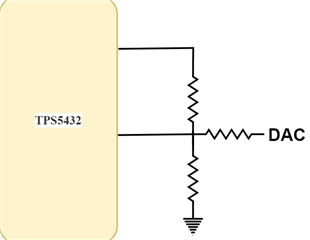
So I am planning to use the DAC of the controller to feed the Vsense pin along with the voltage feedback from the resistor divider from the output of the TPS5432.
2). Is this the correct method to implement the same?.
3). Generally, how is the switching current related  to the output current of a buck converter?.

  • Hi Shibin,

    TPS5432 is a pretty old device. I would recommend to use newer devices instead.

    Do you have a power tree or block diagram?

    What is the switching frequency required? Can the switching frequency be in the range of 2MHz or you need 700KHz itself?

    Would you like to have a device with I2C or VSEL pin for dynamic voltage setting?

    Regards,

    Febin

  • Hi Team,
    Thank you for your reply.
    Attached is the proposed design.


    1). If you can suggest a buck converter that would be great. I am not considering the switching frequency at this moment.
    2). I think a voltage injunction is the simple method to implement the same. So I'm not looking for a I2C controlled buck converter.
    3). My required minimum output voltage is 0.6V. Conyou suggest a buck converter which can achieve this voltage and can be controlled by voltage injunction method?.
    4). Generally, how is the switching current related  to the output current of a buck converter?.
    5). 

  • Hi Shibin,

    There are several methods to adjust the output voltage dynamically and using a DAC is one of them. If multiple rails require voltage adjustment, then a multichannel DAC becomes a more cost- and space-effective solution. Simple systems use a filtered PWM signal or spare MCU analog output to adjust the voltage on one rail. 

    - I would like to propose TPS62825. Please have a look at the datasheet.

    - Could you please re-phrase your question?

    4). Generally, how is the switching current related  to the output current of a buck converter?

    - What is the Application or End-Equipment?

    Regards,

    Febin

  • HI Febin,
    Thank you for your reply.
    TPS6282 seems like a good solution.
    Its output voltage can be adjusted from 0.6V to 4V using the DAC of the MCU or a dedicated DAC.
    1). Is a simple RC filtered PWM signal enough to feed the feedback pin of the TPS6282 in order to adjust its output voltage?.
    2). Most of the DC-DC converters specify their switching current only, how is the switching current related to the output current of a DC to DC converter?.

  • Hi Shibin,

    1. Yes, a PWM signal filtered with a simple RC filter fed into the FB pin through a resistor can be used to control the output voltage. The filtered PWM-signal method requires just a single GPIO pin of an MCU, two resistors and one capacitor. However, every extra rail requires an additional MCU pin and RC filter. This is a drawback compared to the DAC method. DAC method is more practical when you want multiple rails to be controlled. Also, using a DAC instead of a PWM signal gives a cleaner output voltage.

    2. Please have a look at the following App Note. I think this will be useful to understand some basics.

    https://www.ti.com/lit/an/slva477b/slva477b.pdf?

    Regards,

    Febin

  • Hello Febin.
    The adjustable variant of TPS6282 is not available on Mouser or Digikey for 3A or 4A output current.
    So I have completed the design with TPS5432.
    The required output voltage is 1V at 3A of current.
    Could you please review the schematic and let me know if there are any mistakes made.

    The inductor chosen is a 2.2uH inductor. MPN - SPM5030VT-2R2M-D. Its current rating is 6.6A.
    The voltage divider at the VSENSE pin consists of a 10K+49.9 Ohms resistor at the top and a 42.2K resistor at the bottom.
    An output from a DAC is given to the VSENSE pin (not shown) to adjust the output voltage.

  • Hi Shibin,

    The schematic is in accordance with the datasheet recommendations. Looks good.

    Please let me know if you have further questions.

    Regards,

    Febin