This thread has been locked.

If you have a related question, please click the "Ask a related question" button in the top right corner. The newly created question will be automatically linked to this question.

SM72295: HBB shorted to HSB

Part Number: SM72295
Other Parts Discussed in Thread: TIDA-00120, CSD18532Q5B

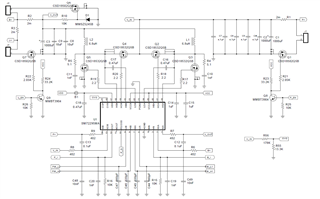
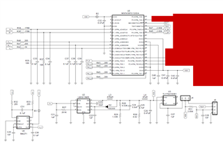
We are having an issue with the SM72295 driver. We have duplicated the TIDA-00120 design for the charge controller, but added additional communications to the MSP430 controller. The problem we are seeing is the SM72295 failing, with an apparent short between HSB and HBB. The resistance between these two pins in the failed state varies, but is always under 100 ohms. The worst we've seen is 19.5 ohms. Working chips seem to have a resistance on the order of a few megohms.

These are new boards that have not yet been used. The first test is applying 24V to the solar panel input. We immediately see 10V at B+. If a 10 ohm load resistor is connected between B+ and ground, VCC sags to about 7.5 volts, and the SM72295 gets hot. There may be a brief period where VCC is applied to the SM72295, but VDD is not yet supplied. This condition lasts for a few seconds during this initial test.

Its not clear to us what the failure modes of the SM72295 are in this type of circuit that would cause VCC to be shorted from HBB to HSB.

We have previously produced several PCBs of the same design that do not have this issue. About 60% of the new batch have this failure mode. Is supplying VCC without VDD to the SM72295 sufficient to cause this failure? The fact that some boards work perfectly fine, and some boards fail catastrophically has us stumped.

  • Hi Jonathan,

    Please send your schematic for review.

    Also I have a couple questions in order to clarify the situation

    1. Is the VCC sag and chip heating observed before VDD is available?
    2. Is B+ HOB or HIB or something else?
    3. is 10V seen at B+ on all boards or just the shorted ones?

    Thanks,

    Daniel W

  • Hi Daniel,

    The schematic is identical to the one given in TIDA-00120 (PMP7605) document. 

    (Red areas are modified from reference design. In the context of the test, only pins 24 and 25 of the MSP 430 are used for off board UART communication.)

    1. It seems so. We specifically tested a few boards by applying 24V to J1 in the schematic before providing VDD. Some failed, some were fine. On the boards that do not have a short, it doesn't seem to matter if VCC is 10V and VDD is absent.
    2. Sorry, B+ was a reference to the schematic, please see above. If the DC-DC converter were operating normally, B+ would be 12V during the initial test. However the first step of the test performed by the MSP430 is to check the B+ voltage and bail if it is too high. Bail meaning set all pins appropriately for no-operation and wait(1). The startup code on the MSP430 also checks that the current through R1 and R2 are low and also bails. If the short is present, there is a measurable current through R2. So PW_L1, PW_L2, PW_H1, and PW_H2 are never toggled high.
    3. 10V is only seen at B+ on the boards with the shorted SM72295 chips. On working boards B+ usually floats to between 2-5 volts. I surmise this is due to a little bit of leakage current charging C3, C9 and C8.
  • Hi Jonathan,

    Is the test described in 1. causing the failures or an observation after? If it is the cause, what voltages are being provided to the driver (i.e. VCC, inputs, etc.) before or with J1 if any.

    Thanks,

    Daniel W

  • Hi Daniel,

    Your question spawned a quick test that we're still investigating. We tested the resistance between HBB and HSB before and after applying first VDD, then VCC, and saw no change in resistance. So it suggests there is some aspect of the test that is causing the failure. Bear with me while we investigate this further.

    The voltages applied to the driver are 10V VCCA/VCCB, 3.3V VDD. HSA and HSB will see about 12V during the test, but would go up to about 15V in their intended application. SIA/SOA would be about 12V. SIB/SOB see 24V. LIA, HIA, HIB, and LIB see 3.3V logic. OVS sees about 1.7V.

  • Hi Jonathan,

    Thank you for the update. Please let me know what further findings or questions this testing brings.

    Thanks,

    Daniel W

  • Hi Daniel,

    I think we've figured out our problem. It seems like the mosfet we used (Infineon ISC027N10NM6ATMA1) is just a bit too different from the TI component specified in the reference design (TI CSD18532Q5B). This lead to ringing during part of the functional test. My guess is the transient negative swing on HSB exceeded the -5V tolerance of the SM72295 on the HSA/HSB pins. I guess the >15V across the driver is what can cause HSB to short to HBB?

    HOB:

    HSB:

    So, it had nothing to do with the order in which VCC and VDD were connected.

    Do you have any guidance on what the right solution is here? I had thought these two mosfets were pretty close in terms of their datasheets. TI's SLUA887 https://www.ti.com/lit/an/slua887/slua887.pdf?ts=1650507089213 suggests I need a slightly larger bootstrap capacitor based on the scaling of Equation 1, but the numbers don't make sense to me. Using that equation would give ~.052 uF for the 44 nC of the TI mosfet, but the TIDA-00120 specified 0.47 uF, almost 10 times bigger than that. 

    I had a few TI CSD18532Q5B Mosfets left over from prototyping, and the problem went away after swapping those in.

    HOB with TI MOSFETS:

    HSB with TI MOSFETS:

    I would like to understand what adjustments would be needed to work with the Infineon MOSFET due to supply chain availability.

  • Hi Jonathan,

    Thank you for the detailed response. I will review the information and get back to you tomorrow.

    Thanks,

    Daniel W

  • Hi Jonathan,

    One thing to try would be to increase the gate resistances (R17-20). this should reduce overshoot on HS. This is probably the easiest solution to test. Another solution could be to add a clamp diode from ground to HS.

    I would not expect any change to be necessary with the bootstrap at this time.

    Additionally, it would be helpful if you can get a scope shot of HO wrt HS with the Infineon FETs.

    Thanks,

    Daniel W

  • Hi Daniel,

    Thank you for the tip. I will test this in a day or two, just busy working on something else at the moment. I will mark the issue resolved, as I think I have what I need. However, I'll get you those scope views and would like to carry on the conversation a little bit.

    Thanks,

    Jonathan