Other Parts Discussed in Thread: LM5013, LM5013-Q1, LMR38020, LM5012
Hi.
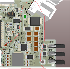
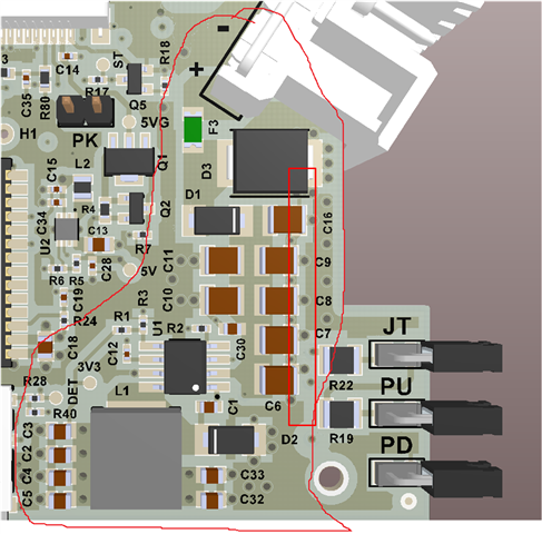
Here is the schematic:
Some of the calculations:
------------------------------------
FEEDBACK RESISTORS
------------------------------------
Vin = 10~65V
Vout = 3.3V
Iout = 3A
Vfb=0.75V
Relationship = (3.3-0.75)/0.75 = 3.4
Resistors = 150R/510R
Vout = 0.75+0.75*(510/150) = 3.3V
Power.Rup = (2.55^2)/0.51 = 6.5mW (ok)
------------------------------------
SOFT-START CAPACITOR
------------------------------------
tSS(ms) = CSS(nF) * VREF(V) / ISS(uA)
tSS(ms) = 1 * 0.75 / 3
tSS(ms) = 0.25ms, 250us
------------------------------------
UVLO/EN
------------------------------------
Vstop = 8V
Vstart = 9.4V
Ihys = 3.6uA
Ien = 1uA
Ven = 1.2V
RenT = (Vstart-Vstop) / Ihys
RenT = ( (9.4-8) / (3.6*10^-6) )
RenT = 388.8K ohms = 390K ohms 1% 0603
RenB = ( Ven / ( ( (Vstart-Ven) / RenT ) + Ien ) )
RenB = ( 1.2 / ( ( (9.4-1.2) / (390*10^3) ) + (1*10^-6) ) )
RenB = 54.48K ohms = 56K ohms 1% 0402
------------------------------------
SWITCHING FREQUENCY
------------------------------------
--> 550KHz
RT[Kohms] = 42904 * (fsw [KHz] ^ -1.088)
RT = 42904 * (550^-1.088)
RT = 44.76K
Chosen RT = 44.2K 1% 0402
------------------------------------
INDUCTOR
------------------------------------
Lmin = ((VinMAX-Vout)/(Iout*KIND)) * ((Vout)/(VinMAX*Fsw))
Lmin = ((65-3.3)/(3*0.4)) * ((3.3)/(65*550000)) *10^6
Lmin = 4.74uH
L = 6.8~10uH
Chosen L = 6.8uH +-20%
6.8uH*0.8 = 5.44uH (6.8uH with -20% de tolerance)
5.44/4.74 = 1.14
------------------------------------
MAXIMUM SWITCHING FREQUENCY
------------------------------------
Chosen inductor = IHLP3232DZER6R8M11 (Vishay)
- Irating = 7A, Isat = 6.7A
- DCR = 33.4mOhm max
fsw(max) = (1/tONmin) * ( (Iout*DCR+Vout+VD) / (VinMAX-Iout*RDSon+VD) )
fsw(max) = ( (1/(90*10^-9)) * ( (3*0.0334+3.3+0.6) / (65-3*0.32+0.6) ) ) / 10^6
fsw(max) = 687 KHz
550KHz / 687KHz = 0.8
------------------------------------
-----> DIODE TVS AT THE INPUT
- Description: Diode TVS of 60V, 5kW, SMC package, PN: Any one with prefix 5.0SMDJ60CA
- Reverse Stand off Voltage VR (Volts): 60V
- Maximum Reverse Leakage IR @ VR (μA): 5uA
- Breakdown Voltage VBR (Volts) @ IT, IT = 1mA: 66.7V Min, 73.7V Max
- Maximun Clamping Voltage VC @ IPP (10/1000μs) (V): 96.8V
- Maximum Peak Pulse Current IPP (10/1000μs)(A): 51.7A
- Maximun Clamping Voltage VC @ IPP (8/20μs) (V): 125.1V
- Maximum Peak Pulse Current IPP (8/20μs)(A): 387.8A
Would it be better to switch the TVS by a varistor? Or another protection component?
Other obervations about the TVS?
------------------------------------
-----> FUSE AT THE INPUT
- 2A, 63VDC, 1206, Slow blow response time, PN CC12H2A-TR (Eaton)
- DC Cold Resistance = 0.1 Ohms
- Breaking Capacity @ Rated Voltage = 50A
- Melting I2t = 1.1
Any observation about the fuse?
------------------------------------
-----> INPUT DIODE AND FREEWHEELING DIODE
- PN MBRAF3200T3G
- 200V, 3A
------------------------------------
-----> INPUT CAPACITORS
- 1x 100nF, 100V, 0603
- 7x ceramic 10uF, 75V, 1210
- Description: Capacitor ceramic SMD, 10uF, 75V, 1210, X7R or X5R, PN CGA6P1X7R1N106K250AC or CGA6P1X7R1N106M250AC or C3225X7R1N106K250AC, all these PNs are from TDK Corporation
------------------------------------
-----> OUTPUT CAPACITORS
- 1x 100nF, 50V, 0402, Low ESL
- 6x ceramic 47uF, 10V, 0805
- Description: Capacitor ceramic SMD, 47uF, 10V, 0805, X5R, PN GRM21BR61A476ME15L (Murata)
------------------------------------
My main doubt is, as the absolute maximum input voltage of the buck IC is 65V, I wanted an opinion if fast voltage spikes/peaks/surges at the supply input could damage the buck IC, and what could be done/improved/changed in the design regarding this. I wanted an opinion about this design. I really wanted that LM5013 chips were already on the market so I could use it in the place of LMR16030.
Regards,
Jeferson.