This thread has been locked.

If you have a related question, please click the "Ask a related question" button in the top right corner. The newly created question will be automatically linked to this question.

LM3409: Drastically lower output current than expected

Part Number: LM3409

I'm developing an application that uses an LM3409 to drive a strip of 8 LEDs with a combined voltage drop of 25V with a current draw of 360mA (+- 25%) from a power supply at 28V. I am targeting a frequency of 462khz, with a TOFF of ~120ns. I have derived the following values for my passives from the datasheet math:

Duty cycle @ 95% efficiency: 25 / (0.95 x 28) = 0.94

TOFF: -28 (4.7e-10 + 2e-11) x Ln(1 - (1.24 / 25)) = 1.3e-7

Fsw: (1 - 0.94) / 1.3e-7 = ~462,000

ROFF: 5.2kΩ

Imax = 0.36 + (0.36 * 0.25) = 0.45

Rsense: 1.24 / (5 x 0.45) ~0.55Ω

I'm also using a 47µH inductor, which is larger than required, but reduces my costs for reasons relating to the way the assembly is priced. In order to test my design, I created a layout which essentially duplicates the LM3409 evaluation board, but using my own values for the passives. The issue I am encountering is that the board is powering the LEDs at a much lower current than the value of Rsense should produce. Just for a sanity check, I swapped Rsense for the 0.2Ω resistor that the evaluation design uses, and the board emitted the correct current, although the VIADJ control was extremely non-linear.

The value I am seeing with an Rsense of 0.55Ω is ~10mA, which is dramatically lower than the 360mA I should be seeing.

I took some measurements with my oscilloscope, and this is what I am seeing:


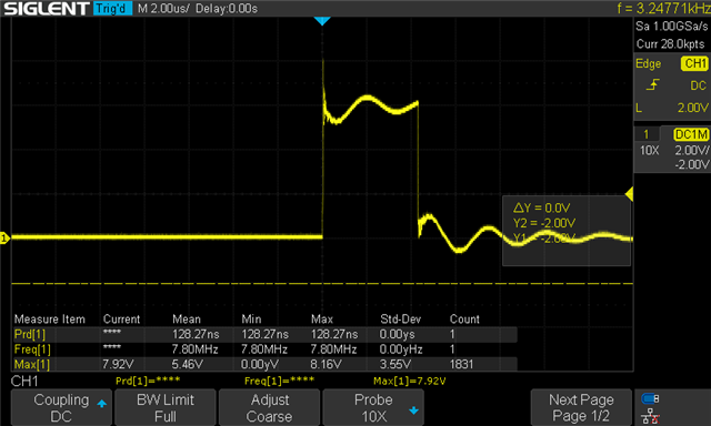
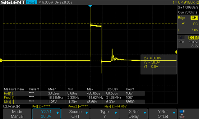
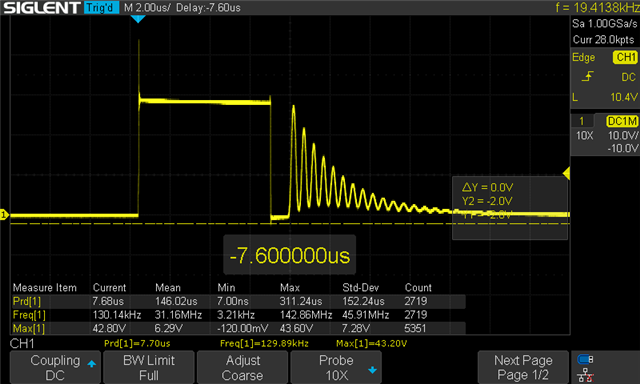
With the scope probe ground on the gate of the PFET and the probe on the source, I'm seeing a roughly 130ns pulse, which makes me think the timing is being set correctly.

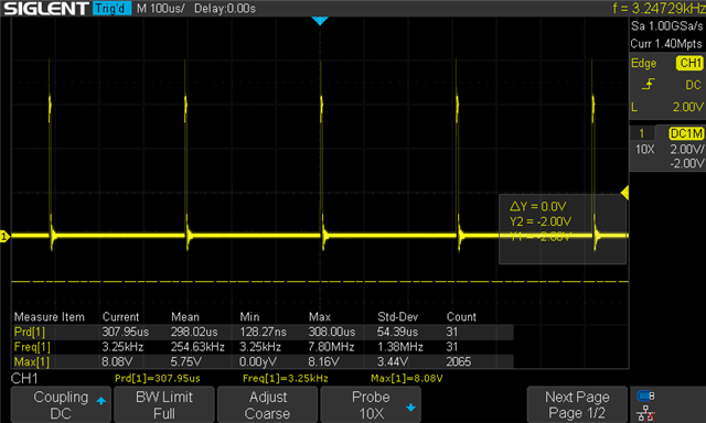
The TOFF however, appears to be on the order of 300µs, which puts the overall frequency at ~3.25khz. From what I could derive from the datasheet, the TOFF is determined by the measurement of the voltage drop across Rsense.

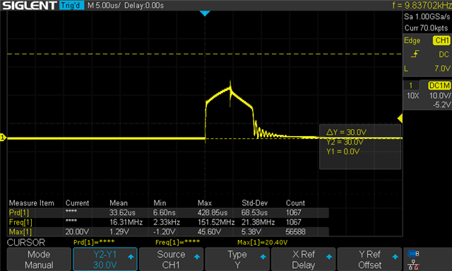
With the probe ground on the circuit ground and the probe on the SW node, I see a fair bit of ringing, though I'm not sure that would cause the problem I am seeing.

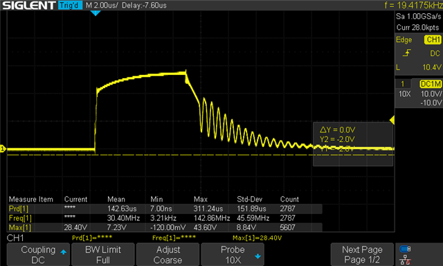
With the probe on Vout the peak voltage looks right, but the pulse is again much too short to produce the desired current output.

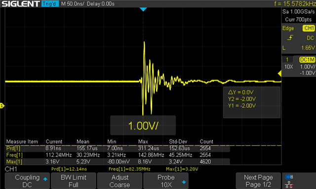
For a sanity check I probed VIADJ, and I am seeing an odd pulse which I assume is noise from elsewhere in the circuit. The voltage reads as 1.23V on my DMM however.

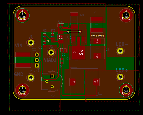
For reference, this is my board layout, which you can see if heavily derived from the evaluation design.

  • Hi,

    From the SW waveform, it looks like the SW node is reaching 28V (input voltage) before the current has risen too far. This indicates the resistance of the PFET + sense resistor + inductor is already causing you to go close to the input voltage and current cannot rise further. Effectively this is equivalent to violating the assumption of 95% efficiency because you don't have sufficient headroom.

    To check if this theory is correct, maybe try half the LED string (~10-12V output) to see if you get better results then. It would at least tell us if this theory is correct. Secondly, double check the PFET on-resistance, current sense resistance, and inductor series resistance, and verify that the drop at your desired LED current is <3V, which is the head room you have between 28V input and 25V output. Make sure that there are no other resistances in series.

    The reason you are running at 300usec period is a side effect of the fact that the output is not rising much above 0, and therefore the Toff (which is inversely proportional to Vout) is extremely long (theoretically infinitely long). In such cases the device times out toff at 300usec. which is what you are seeing.

    -Sumeet

  • Thanks so much for your reply! Your theory gave me a few avenues to investigate. Some of what I found indicates that efficiency is playing a part, though I also measured some odd behaviors that seem to indicate that maybe something else is going on?

    I checked the datasheet values for the RDSon on the transistor (0.16Ω) and the inductor (0.0578Ω) which would appear to give me a fair bit of leeway given a 0.55Ω Rsense and ~3V drop.

    I happen to be developing this device for use with red, green and blue LEDs, and I was mostly testing with the green and blue ones that run at around 24-25V per string. I noticed in the datasheet that there is actually a chart that indicates that the efficiency at 28V is actually around 88-89%, and if I plug that into the formulas for determining the switching frequency with an ROFF of 5.2kΩ I get negative numbers, which seems bad.

    I did however have a strip of red LEDs on hand, which draw 360mA at 17V, so I tried out them out and got... pretty much the same result. Which seems odd.

    I also went back to an earlier test, where I swapped the 0.55Ω Rsense for the 0.2Ω that the origin evaluation design calls for, and with the green and blue LEDs the performance seemed to match your description of what was going on. As I increased the IADJ voltage, the output voltage would increase until it hit a point where the frequency was jumping all over the place, after which it would just open the PFET and directly conduct whatever current my supply was outputting. What I did think was interesting was that at no point, even at low currents, was the output continuous. The driver seems stuck in discontinuous mode.

    I then put a 12V string together just for a sanity check, and got pretty much the same result as with the red string. The two measurements below are of the switching node and the output respectively. You can see that even at much lower voltages it doesn't seem to ever trigger the end of TON.

    I think my next step is to test different ROFF values, both the 13.5kΩ I had calculated for the red LED string, and the 15.4kΩ from the original evaluation design. Is there anything additional you would suggest I try? Thanks again!

  • So after some further investigation, I realized that what I was looking when I was measuring the pulse between the gate and source of the PFET at was in fact the _on_ time rather than the off time, but I was getting confused because of the negative voltage. This meant that the issue was being caused by the driver exceeding the maximum off time and shutting down. I replaced COFF and started getting the output I expected.