This thread has been locked.

If you have a related question, please click the "Ask a related question" button in the top right corner. The newly created question will be automatically linked to this question.

LM5045: Synchronization of two LM5045 without microcontroller

Part Number: LM5045
Other Parts Discussed in Thread: SN74AHC1G86-Q1

Hi Team,

In the other E2E thread, a customer synchronized two LM5045 using an external oscillator and a comparator. Our customer would like to synchronize two LM5045 without microcontroller. According to our customer,

We use two LM5045 in our design for more power possibility. We want to synchronize the IC's without using a microcontroller. How is this possible? We tried this by connecting the Rt pin of one controller to the other through the 100pF capacitor. One controller runs at 250kHz, the other one runs at 150kHz. We want to sync them both to 250 kHz without any microcontroller.

Is this solution possible or using an external oscillator is the only solution aside from a microcontroller?

Regards,

Danilo

  • Hello Danillo,

    The datasheet description for the synchronization pin makes be believe it can be done without a microcontroller.

    1) They must have an RT resistor on the "follower" that sets a frequency slightly below 250 kHz.  Maybe try 200 kHz?

    2) Use a 100 pF capacitor to couple "master" frequency into the "follower".  - THEY DID THIS.

    3) The external clock must lift the "follower" RT pin between 3.5V and 5.0V on the low to high transition. - THEY SHOULD MEASURE THIS WITH A SCOPE.

    4) The synchronization pulse width must be between 15ns and 200ns. - THEY SHOULD MEASURE THIS WITH A SCOPE.

    5) Add slope compensation on the "follower" by connecting an appropriate resistor from VCC to CS pin.  Also, disable the SLOPE pin by grounding it.

    So, the main question is: What does the RT pin waveform of the "master" look like?  Can it alone satisfy requirements 3 and 4?  I did not find a typical waveform for the RT pin in the datasheet.

    If the "master" RT voltage is a square wave then requirements 3 and 4 will likely be met.  If the RT voltage is a sawtooth wave then they will probably need to add a couple of transistors to buffer it and create a square-wave (i.e. using REF pin to set maximum value).

    Lastly, if the RT voltage is DC then they will need to generate a square wave from the "master" and couple it into the "follower".  What configuration is their "master", voltage mode or current mode?

    Regards,

    Eric

  • Hi Eric,

    Thank you for your answers to our customer's inquiries. He has further inquiries as follows;

    Hello, our master controller is current controlled system (we use a current sense transformer on the DC line). We did the measurements as proposed. However the Rt-waveform of the master controller is not a square wave or a sawtooth wave, but it is a DC voltage of around 2V. When the controller is active and makes PWM signals, it stays 2V.

    On the other hand is it possible to use the SR1 and SR2 waveforms to create a clock for the RT pin of the follower through the 100pF capacitor. Our system runs at full duty cycle of around 48% for both legs because we don't use the comp pin in our application. SR1 and SR2 pin makes use of 5V reference voltage. May be it is possible to use these signals by ORing them. However the duty cycle will be high 200ns.

    One other question is: We use two controllers for two different full-bridge system which should run at the same frequency. We apply the same Vcc voltage for both, should we use two seperate Vcc voltage for both?

    The Vcc voltage is 12V and we use this external voltage to supply both controllers (master and follower). The main question is that should we apply two different Vcc voltage for the master and the follower IC. or one 12V supply is enough for many controllers? We don't use gate transformers to switch the MOSFET's.

    Regards,

    Danilo

  • Hi Danilo,

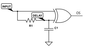
    Using either the SR1 or SR2 outputs is a good start.  However, I would want to limit the duty cycle to something much less than 200ns (see SYNC requirement #4, must have 15ns to 200ns pulse width).  If you want a Master / Follower configuration you could use a single XOR gate along with an RC network to generate a single pulse controlled by the RC time constant (i.e. 50ns to 75ns).  See example circuit below.  The XOR gate will deliver a pulse at the rising and falling edges of SR1 (or SR2).  TI offers a single, 5-pin XOR gate with Schmitt inputs that would be perfect for this - SN74AHC1G86-Q1.  

    Another method would be to incorporate an external clock circuit (555 timer) and AC couple the output to both LM5045's.

    As for the VCC voltages, I think it depends on your application.  A single VCC voltage is simple/inexpensive but you will lose both regulators if the single VCC is lost.  Is this acceptable?  Would there be a benefit to having one regulator down with the other still operating (i.e. two independent VCCs)?

    Regards,

    Eric

  • Hi Eric,

    According to our customer,

    Hello, many thanks for the information. I will design a timer circuit and couple it to both controllers. Can I still use the current control method when we apply the clock pulse from outside. Should we also ground the slope pin and adding a resistor (e.g. 10k) from the Vcc (external 12V) to CS for both controllers? Both controllers will be followers then. For the CS pin, we use on the dc line a current transformer with diode bridge at the secondary side of the CT and connect this to the CS pin with an RC circuit.

    The question about one Vcc voltage for both controllers is actually about the following: Because there are two full-bridge converters, we use the same DC supply and same external 12V Vcc. If we can synchronize these controllers, will be then any problems with the operation of the converters if we use the same Vcc for both converters? This is according to the high side switching of the Mosfet's which use 12V through BST diode. Or the BST diode will protect the 12V Vcc?

    Regards,

    Danilo

  • Hi Danilo,

    You can still use current control method with external sync.  I would follow the datasheet recommendations for setting up the LM5045 with external sync (see below).  It's not clear to me how or where your current transformer and diode bridge are connected.

    There should be local ceramic bypass capacitance on VCC for each LM5045.  The high frequency currents pulled from VCC should be supplied by the local bypass capacitors.  I don't see any issue with a single VCC for both LM5045s.

    Regards,

    Eric