This thread has been locked.

If you have a related question, please click the "Ask a related question" button in the top right corner. The newly created question will be automatically linked to this question.

BQ51003: BQ51003 presents as FOD after charging

Part Number: BQ51003
Other Parts Discussed in Thread: BQ25101,


I see you've answered similar questions to this before and though I would ask you.

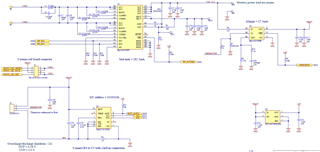
We have a BQ51003 (with a custom PCB receiving coil), and a downstream BQ25101 charging a battery. 

After the battery is charged, the BQ51003 receiver 'turns off' and stops charging. Then the wireless Qi transmitter sees the wearable as a foreign object and goes into fault.

If the device is removed from the transmitting coil the FOD fault on the transmitter is cleared and charging can start again.  

Toggling the enable line (EN1 and EN2) on the BQ51003 does not help to clear the FOD fault on the transmitter. 

The BQ51003 is set to 262.5mA max current, and the BQ25101 is set to 37.5mA output.  Can this difference in currents be an issue, the BQ25101 ~7x less than the B151003?

  • Hello

    Could you send a schematic of your circuit for review?

    After the battery is charged, the BQ51003 receiver 'turns off' and stops charging.

    The BQ51003 will not turn off after charge complete (it is 5V power supply) it must be commanded to turn off by external circuit. How is this done?

    If the device is removed from the transmitting coil the FOD fault on the transmitter is cleared and charging can start again. 

    This may be a function of the TX when to restart after End Power Transfer command, have seen this with some TX.  Have you only tested with other TX?

  • Here's the snap shot of the schematic. I will reply shortly with the other answers.


  • Thanks for the Sch, but resolution is not good.

    Can you repost?

  • Click it to open larger with better resolution.

  • The schematic looks good.  RX coil tuning is set for a coil with Ls' value of about 27uH, does that sound right?

    FOD setting looks good (standard value), how did you determine that the TX was setting an FOD fault?  

  • Regarding the Rx coil tuning, it is set for a Ls' of 27uH.

    The Tx is going into a FOD fault indicated by a red LED. It can be replicated by placing stray metal over the TX coil. 
    We have used this TX with other devices and it did not need the device removed to clear a fault, nor does a fault occur. Also with other TX's we get similar instances of faults happening.

    The Bq51003  is normally left enabled always (EN1, EN2 left pulled down internally, and pulldown resistors). After it reaches fully charged, the TX intermittently goes into a fault at various time intervals; sometimes only a few hours, others after days.  

    When the EN lines are driven low (enable) it is the same as when we don’t drive them and rely on the pull downs. The TX functions for a while, but most units eventually fault.

    When the EN lines are driven high (EN1=EN2=1, disable), the TX unit consistently faults.


    For our case is there any benefit to driving the EN lines to 01 (EN1=0, EN2=1, Table4)?  Giving priority to the wireless, and disabling the adaptive comm limit?  

    Also there are extra pieces of metal in the TX 'field of view' (brass threaded inserts, and a PCB loop antenna) that aren't fully shielded by the ferrite backer of the RX coil.  Could these be leading to FOD issues on a TX?

  • The Tx is going into a FOD fault indicated by a red LED. It can be replicated by placing stray metal over the TX coil.

    The FOD setting is Ros, R2 from RECT to FOD this will adjust FOD setting at low output current.  Value is 20k and can decrease value to 16k.  Also R-FOD, R5 will adjust FOD at higher current. Value is 232 ohms, it can be increased to 250.

    But FOD problems at this low a current are not common.  Is the PCB or battery exposed to AC field from TX?  Using shielding material can be added between the coil and PCB/Battery can control AC field and reduce FOD loss.  One type is Wurth Electronics 354002.

    For our case is there any benefit to driving the EN lines to 01 (EN1=0, EN2=1, Table4)?  Giving priority to the wireless, and disabling the adaptive comm limit?  

    This would not help.

    Also there are extra pieces of metal in the TX 'field of view' (brass threaded inserts, and a PCB loop antenna) that aren't fully shielded by the ferrite backer of the RX coil.  Could these be leading to FOD issues on a TX?

    Yes this is a possible problem.  Something is causing the TX to see a high loss, metal in the AC field.  Shielding can possibly help.

  • I tried reducing R2 (Rect to FOD) to 16kR and R5 FOD to 250R, the TX still went into a FOD fault.  

    Unfortunately, we are likely unable to make shielding changes at this point.

    Any further suggestions?

  • As a test -- extend the coil on short lead wires so that it is separate from the case.  Then place only coil on transmitter.  This will confirmation what area is causing the problem, coil only should work.  Then add antenna, hardware or other metal around the coil to determine which one is causing the problem. 

  • I will do my best on this but it will be difficult for us to do this.  Many of the components are nested and glued together.

    Is there a limit to how large R_FOD can be?  For instance does increasing it to 1kR potentially harm the BQ51003?  What determines its proper value? 

  • The problem is power dissipated in unit.  It appears something in the AC field is absorbing a lot of energy.  If R_FOD is set high unit may charge but something in unit may overheat, possible hazard.

    Do you have a coil that is not installed, disconnect installed coil and wire in the extra coil.

  • I was able to build a setup with a coil and no brass threaded inserts or screws. Testing with this the TX has not yet tripped, how ever sometimes the trip takes days to happen. 

    I also tested the following:
    R5 (FOD) increased to 500R, R1 changed to 800R. Tx still trips.
    R5 (FOD) increased to 1kR, R1 changed to 300R. Tx still trips.  
    These were attempts to turn off the FOD function of the Rx.  
    Regarding an object absorbing energy, it is most likely the brass threaded inserts, but they have not been seen to get warm.  And they will be costly to remove them from the field of view of the TX at this point. 

  • Would it be possible to work with you using the PM feature of the forum?

    I will contact you.