This thread has been locked.

If you have a related question, please click the "Ask a related question" button in the top right corner. The newly created question will be automatically linked to this question.

UCC28712: UCC28712 replacing UCC28711

Part Number: UCC28712
Other Parts Discussed in Thread: UCC28710, , UCC28711, UCC28780

Hello

We have a module use generally use UCC28710 dbr and it works fine.

Due to shortage , we bought some UCC28712 thinking it should make no difference because we do not use NTC or CBL COMP

NTC pin is open while with 28710, we use 10 k on pin 3

Strangely , 28712  suffers a huge efficiency loss and it is 50% lower at 250vdc input. 
I have failed to figure out why !

Out of a Lot of 10, 5 are with 28712 and each has 50% loss in efficiency - cannot be a random reason!

Any help in the matter will be highly appreciated

r

  • Hi, Robin:

    Would you please share the test condition of the efficiency test? And share the VDS, VCS ( or IDS) waveform as this condition according to both UCC28710 and UCC28712?

    UCC28712 has fixed cable compensation, but UCC28710 is programmable. The cable comp may impact the switching frequency to cause higher lost. 

    Regards, 

    Wesley

  • Wesley:

    Thanks first of all for the prompt reply.

    We have a test fixture. So we were testing these modules one at a time… in exact sane setup- 5 gave us 85%, 5 yielded 49%.. 

    The only difference we could find was these 5 had ‘12 while higher eff had ‘10 .

    We had 10 k at pin 3 in all.

    When I noticed we had ‘12, we removed 10k.

    Retested: same 49% 

    I will try to measure items you mention today & report.

    thnx much

  • Hi, Robin:

    Pin3 of UCC28712 is NTC.  10kohm does not impact power consumption too much. INTC is only 105uA as typical. Power loss of 10kohm is 0.1mW around.  Check IDS and VDS can help us identify their switching loss and conduction loss at the same load condition. Both of them may impact efficiency more than NTC resistor I think. 

    Looks forward with your investigation and see if we can find any clue from the waveform. 

    btw, may I have your test condition of efficiency test? 

    Regards, 

    Wesley 

  • Wesley:

    We seem to be working thru  the night!

    I will send test sch and other info asap

    thank you so much.

    r

  • Wesley:

    There SEEMs to be a problem : take a look at the voltage  filtered) across RCS. attached.

    See attached xl spreadsheet calculations as well.

    We have made these modules a lot: generally, we obtain excellent load/line regulation, and efficiency. So we no longer test for Vrcs. In fact the highest efficiency we have seen is 89%. We use a HV GaN switch.

    Transformer is EQ20, Ae=55 mm2, Np=36, Ns=3( for 6v output), Na=10

    We do have a second output of 22V as well. We obtain excellent cross-regulation.

    Yet, we see slight "saturation ".

    There must be an issue I need to address immediately.

    In the UCC28711 ds, I do not see a detailed startup and how the controller gets in a steady state. Here is my recollection from first encounter with this controller: it sends out the first 3 pulses, each 2usec wide.

    If all goes well, It sends out 5 pulses: now checking for VS pin. 

    This is very similar to UCC28780. Where is it explained step by step.  Not in UCC28711 ds though.

    So with 47.5% max duty, assuming that happens at Vmin- 105V here- max Pulse width will be 4.75 usec at 105.

    That comes to .233 T, no chance you get even close to saturation especially when there is enough gap & current is low.

    At 250V, one would estimate 1usec pulses, right? No chance of saturation here either.

    Pl see attached Test ckt. 

    We hope to find a root cause of this asap.

    thnx

    UCC28712ASSY_SATURATION.pptx

    rUCC28710-module1_ti0421.xlsx

    EQ20Test_fixture.pdf

  • Wesley:

    I was reviewing the calculations one more time & the startup event: so I think that our xmfr has too little gap- Lpri is like 770uH, the calculated value is 350uH. Since the controller turn ON depends on getting to the Ipk(pri), then it will exceed ON time max allowed at high input voltages- which leads to saturation.

     we are going to try out with 350uH by increasing the gap.

    Will report back Monday

  • Hi, Robin:

    For start-up process of UCC2871x series, IC would send 3 initial pulse after VCC reaches VCC(on) threshold. The 3 initial pulse width is limited by VCST(min). After these 3 pulse, UCC2871x would operate according to the control law. The converter will remain DCM operation during charging output capacitors, maintain constant current output until output voltage is regulation.

    As your RCS is 0.75ohm in the calculator. The IPP would be around 0.2V/0.75=0.26A. The current which made by initial pulse would not make transformer saturated. Also, the on time you share in the waveform is around 5us, which is also much wider than the initial pulse. So yes, I agree with you that problem may come from transformer.

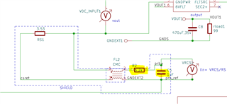
    Another weird point is the VCS voltage is very small. It shows 5mV/div in your waveform. If the scale is correct, RCS value is incorrect. And I saw C5 (1uF) is in parallel of VCS in your schematic. Is C5 a VCS filter? 1uF is too big to use as filter. It makes the waveform distortion. Maybe it could be another reason to make high Ipeak since the IDS*RCS can not reaches to VCST(min) in expected time. So, please check the VCS related component value is proper or not..Thanks.

    Regards, 

    Wesley

  • Wesely:

    Yes: I think the probe used to measure is funky. Problem with scaling I put in the Siglent scope. We had to doctor up the probe tip in order to use the probe tip GND metal without using GND lead wire. Removing the tip portion does not give the correct 1:1 scale.

    Or perhaps poor connection to the test pin we have at Rcs.

    Here we're interested in looking at the Vrcs shape. Definitely saturating.

    No matter how you calculate, with Ae=55 mm sq, Npri=36, Ipk from spreadsheet= .9 A, there is no way to go even close to Bsat with Max duty=47.5%

    Yet, surely,  there is something not quite right with the transformer. These are planar on PCB: so hard to dig into what exactly came out of the 12 layer PCB. Yet, 5 of the lot of 10 performed excellently. In fact , wired version we built during initial Eval kit verification of our design with 60:5:5 and GaN, gave us a proto with 95% efficiency, not kidding....but not reporting either...Planar coil could not give us more than 36T which is deemed sufficient. We did sacrifice efficiency by 6-8% due to this.

    We are looking into the xmfr ...

    The First will be to get Lpri=350 as calculated in the spreadsheet.

    thnx. 

    Until Monday.

  • Hi, Robin:

    Thanks for your explanation. Looks forward the test results of Lpri=350uH.

    Regards, 

    Wesley.

  • Hi, Robin:

    I would like to close this thread since you already find the root caused. Thanks.

    Regards,

    Wesley