Team e2e,
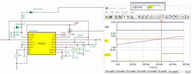
I am simulating ISO5451 model in TINA TI. Acc to the datasheet, the input hysteresis voltage at IN+ is typically 0.15 * Vcc1 -->

In my test case, Vcc1 = 5V, hence hysteresis V = 0.75V, which means that the switching voltage should be between 2.25 (min 0 to 1) and 2.75 V (Max 1 to 0).
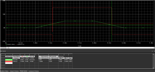
When I verify this in TINA with triangular wave at the input (instead of sq wave), I see that the driver changes state from 0 to 1 at 2.5V -->
Is there something I am missing here ?
Attached is the TINA file.
Thank you,
Anubha