This thread has been locked.

If you have a related question, please click the "Ask a related question" button in the top right corner. The newly created question will be automatically linked to this question.

BQ51013B-Q1: BQ51013B-Q1 FOD calibration issue

Part Number: BQ51013B-Q1

We have integrated the BQ51013B-Q1 wireless receiver into a custom hardware design but our design has variable performance when attempting to operate with off the shelf charging pads. In some cases the device will not charge at all.

We believe that this issue may be due to the foreign object detection feature.  We would like to perform a FOD calibration but it appears that the recommended calibrated transmitter is no longer available.

Are there updated guidelines, FOD calibration app and alternate transmitter kits that we can use to complete this work?

The design is using a Wurth dual WPT/NFC coil (Part # 760308103307).

Thanks.

  • Hello

    Couple of changes to the FOD circuit may help but need a little more info on your system:

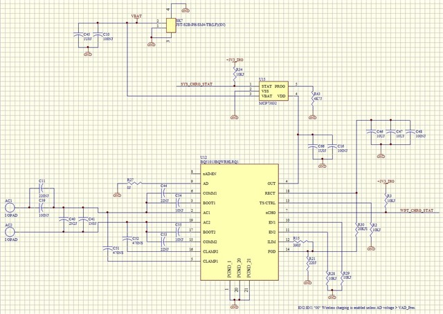
    1.) Can you send a schematic for review?

    2.) What is the max output current?

    3.) Does the physical design have any metal around the coil or in the AC field from TX?  Is the PCB and battery shielded by Coil?

    4.) Is this unit Qi certified?

  • Hi,

    1) Schematic

    2) The battery charge current requirement is 200 - 300mA.

    3) The coil is mounted flat on the inside face of a plastic enclosure.  This spaces the coil 2 - 3mm from the surface of the charging pad.  There are two physical product variants - in one the PCB is adjacent to the coil and in the other the battery is adjacent to the coil.  There is no additional shielding apart from the ferrite in the coil assembly.

    4) This unit does not require Qi certification.  The charger pads that we have been testing with are certified.

  • Hello Brian

    Thanks for the additional information.

    Could of things to look at:

    1.) If the PCB is located near coil it could appears as a foreign object to the transmitter AC field.  Magnetic shielding material will help to control the AC field, we have used Wurth Electronics 354002.  This can be placed between the coil and PCB.

    2.) Two resistors on the PCB control power reported to transmitter for FOD, R21 (R-fod) = 220 and R30 (Ros) = 20k.  Can try increasing R21 to 240 to 250.  

    3.) Coil L value of 7.8uH is on the low side, this will cause transmitter to generate a larger AC field that will aggravate any FOD issues.  If possible increase coil L.

  • Hi Bill,

    Thanks for the feedback.

    We have done some experimentation with changes to R-fod but we did not see much improvement.  

    What would be your suggestion for a target for coil inductance for this application?

    Do you have a suggestion for a calibrated transmitter that would allow us to perform the FOD calibration?

  • Hi Brian

    As a test try extending the coil on leads and only place the coil on the transmitter.  This would indicate how much the metal around coil in contributing to FOD fault.

    What would be your suggestion for a target for coil inductance for this app

    I would recommend about 12uH to 15uH, but can be higher.

  • Hi Bill,

    I have tested the unit with the coil located away from the PCB and the battery and the behaviour is similar.  The main parameter that influences the performance is the distance between the coil and the surface of the transmitter.

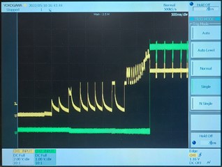
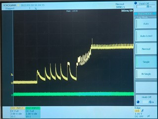
    Below are oscilloscope traces showing captures of the Vrect(yellow) and Vout(green) signals.

    1. The rx coil is placed directly on the surface of the transmitter.  The system functions and charges the battery

    2. The rx coil is spaced approx. 2mm above the surface of the transmitter.  The wireless power transfer system appears to cycle attempting to retry the handshaking process.  Vout is never activated.

    • Do these waveforms look ok to you?
    • What causes the periodic (200msec) events with the decaying profile on the falling edge prior to the start up phase?
    • Is the activity on the Vrect and Vout signals after the start up phase just ongoing communications? 
  • Hi Brian

    The voltage at RECT needs to reach 7V for the OUT to enable, good one is, bad one is not.

    This could be due to communications or the TX reaching max power.

    Communications -- try increasing Comm1 / Comm 2 caps to 44nf

    TX reaching max power -- this is harder but check operating freq, many TX will  change freq to control output power.