BASIC_V0.50.pdfBASICPWR_V0.60.pdf
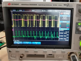
BASIC_ V0. 5 is the previous design, basicpower_ V0. 6 is the current design. The design of version 0.5 can realize the stable output of 19v 0a-9a. The design of version 0.6 has three PCBs and the inductance is 10uh 14a. At present, the output is unstable during debugging, as shown in the waveform diagram;
1. We changed the output capacitance to 100uF / / 1uF, but the situation has not improved;
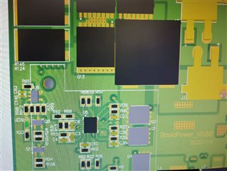
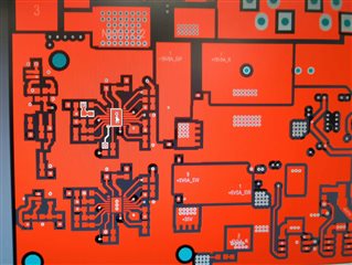
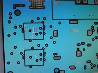
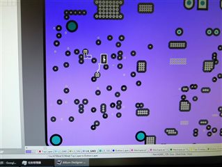
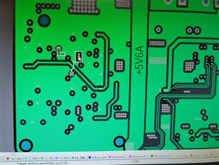
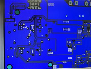
2. We compared 0.6 version of PCB with 0.5 version of PCB, and there was little difference; As shown in the figure, it is a 0.6 version of PCB, with red as the top, dark blue as the bottom layer, light blue as the second layer, with ground wire, purple as the fourth layer, and the rest as the signal layer;
3. The frequency of version 0.5 is 300kHz and that of version 0.6 is 588khz. We adjusted the frequency of version 0.6 from 588k to 305K, but the situation has not improved;
Please give suggestions. What may be the problem? What kind of tests do we need to locate the fault point?
