This thread has been locked.

If you have a related question, please click the "Ask a related question" button in the top right corner. The newly created question will be automatically linked to this question.

TPS2373-4EVM-758: Synchronous rectification - reverse voltage protection

Part Number: TPS2373-4EVM-758
Dear Sir,
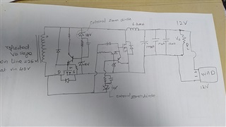
  • I have issue with the transistor based synchronous rectification in forward converter. When customer connects wall adapter to Target board, The reverse voltage to our board has damaged the sync fets.
  • how to protect the Mosfets from reverse voltage? is there any solution for this ?
  • Can you pls guide me how to resolve this issue.?
  • Hello, 

    Yes this is a well known issue with synchronous rectification. Special attention needs to be given to protect the FETs. I would suggest a Power MUX 

    See our Advanced ORing options

    If this post answers your question, please indicate so by marking this thread as resolved. Thank you.


    Regards, 


    Michael P.

    Applications Engineer

    Texas Instruments 

  • Dear Mr.Michael,

    I have an idea to turn off the mosfet using the zener diode(in below diagram) when customer connect wall adapter in our board. I have implemented this circuit on our board. but it is not working. Means, dispute the zener diodes, short created at the fets if reverse voltage applied (tested on 12V boards).
    I have enclosed the circuit diagram used  for  this protection, for your reference.
    Customer will use either PSE or Wall adapter they will never connect both the supply on same time. So If it is powered from PSE the Min reflected voltage on the transformer is 25V, this is enough to drive the gate in forward Mode. I have connected the external 14V zener (Which i have mention on the diagram) to NPN transistor base terminal. When the customer connect the +12V Wall adapter (In reverse Mode) mosfets should not turn ON. But this circuit has not functioned as expected.
    Can you pls guide me how to resolve this issue.?
    Thanks in advance.
  • Hello, 

    I cannot comment on your personally designed circuit, but I would suggest either using a power mux, or can you just use a blocking diode on the output? Would a diode on the output of the 6.8uH inductor work to block the 12V adapter?

    If this post answers your question, please indicate so by marking this thread as resolved. Thank you.


    Regards, 


    Michael P.

    Applications Engineer

    Texas Instruments