Hi Team,
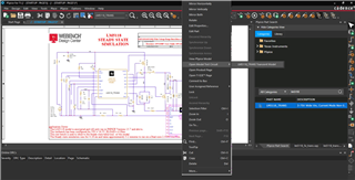
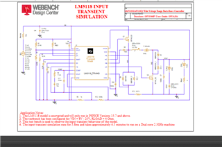
I need help in to clarify the connection made to LM5118 transient simulation schematic.
May I know why you used V_Icout, V_Iinductor, and 0Vdc in the schematic.
Thanks in advance.
Regards,
Marvin
Hi Team,
I need help in to clarify the connection made to LM5118 transient simulation schematic.
May I know why you used V_Icout, V_Iinductor, and 0Vdc in the schematic.
Thanks in advance.
Regards,
Marvin